Project 08
Case study on Failure of Aircraft Composites and Alternative Manufacturing Approaches
A manufacturing case study tracing delamination, voids and fatigue failures in aircraft and wind-turbine composites back to hand lay-up and vacuum infusion, and matching each failure to prepreg, resin transfer molding or carbon-fibre 3D printing.
Project overview
From failure evidence to process selection
Documented failures in UAV structures, aircraft cabin panels and wind-turbine blade roots were traced to their manufacturing root causes, then compared against advanced manufacturing alternatives to recommend a better-suited process for each component.
01 / Context
Composites and conventional processes
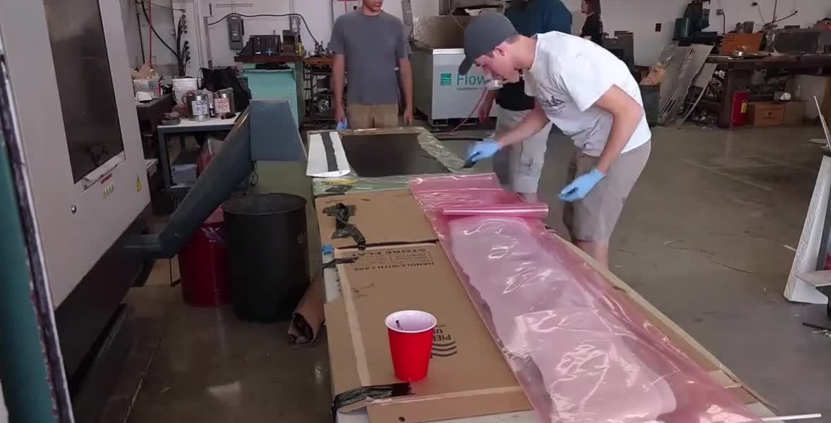
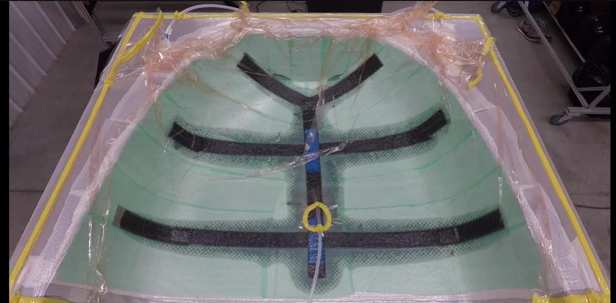
Composites offer a high strength-to-weight ratio, corrosion resistance and design flexibility, and are used in primary and secondary aircraft structures (fuselage, wings, fairings). Wet (hand) lay-up applies liquid resin manually over the reinforcement before curing. Vacuum infusion places dry reinforcement in a mold and draws resin through it under vacuum pressure.
02 / Failure cases & root causes
Three documented failures
Case 01
UAV wing skins & empennage panels
Composite UAV wing skins and tail panels
Observed failures
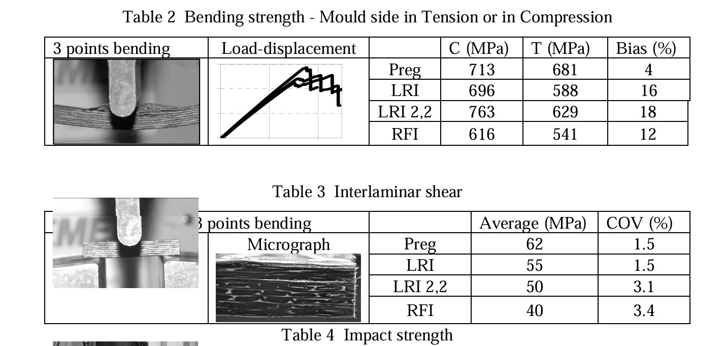
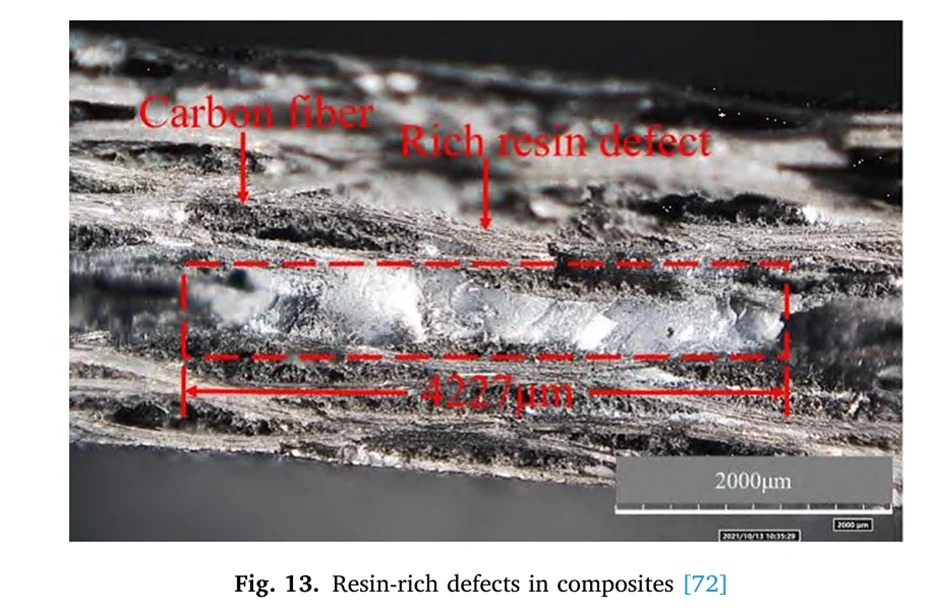
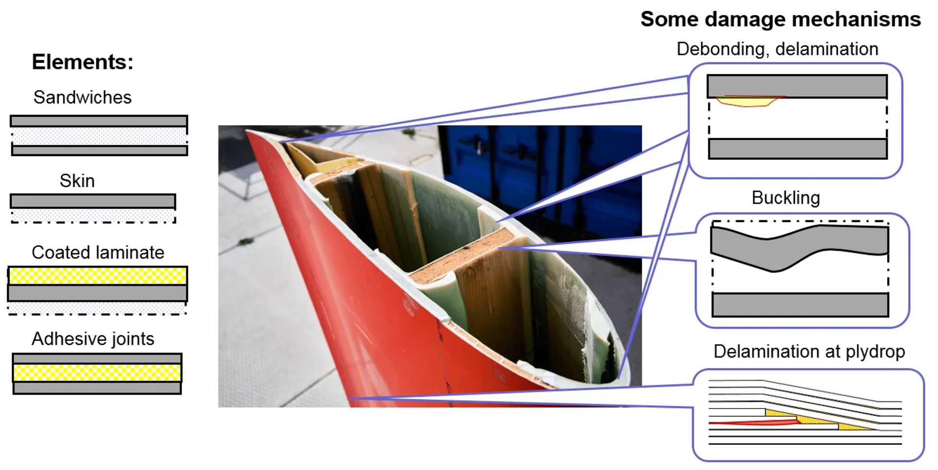
Premature buckling under aerodynamic loads and delamination during in-flight trials. Low compressive strength: 63.66 MPa for hand lay-up (HLU) versus 109.06 MPa for vacuum resin infusion (VRI). Low shear strength with HLU: 13.06 MPa versus 16.88 MPa for VRI.
Source: researchgate.netRoot causes
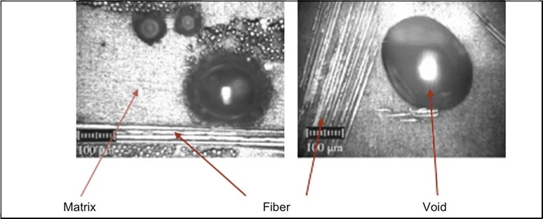
High porosity and voids from air entrapped during HLU and VRI, lowering mechanical performance. Limited fibre-volume-fraction control: aerospace parts need ~60%, while HLU and VRI reach only ~50%, reducing stiffness and strength. Excess resin content adds weight and reduces structural efficiency.
Source: ecm-academics.plymouth.ac.uk
Case 02
Aircraft lavatory wall panels & overhead bins
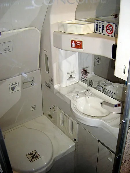
Lavatory side-wall and ceiling panels; overhead stowage-bin covers
Observed failures
FAA-reported 16% rejection rate due to delamination, disbonding and voids. Structural cracks around fasteners, plus surface waviness and poor finish.
Source: federalregister.govRoot causes
Manufactured by hand lay-up: manual fibre placement produced non-uniform thickness. Air entrapment from inadequate compaction.
Case 03
Wind-turbine blade roots
Root section of large wind-turbine blades
Observed failures
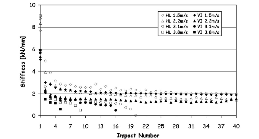
40% reduction in fatigue life for hand lay-up laminates.
Source: sciencedirect.comRoot causes
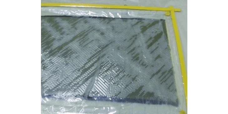
Wet lay-up achieves only ~50% fibre volume fraction, reducing stiffness and strength. Entrapped air and poor compaction in hand lay-up. Early resin gelation and vacuum leaks in vacuum infusion.
Source: mdpi.com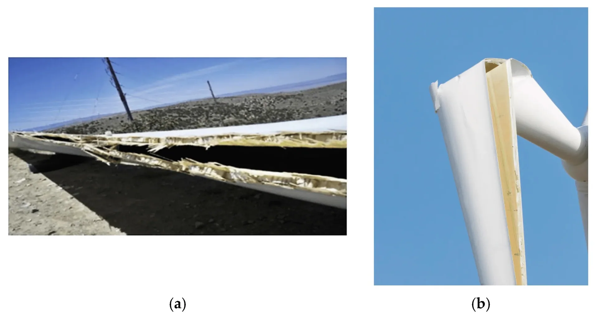
03 / Alternative methods
Why change the process
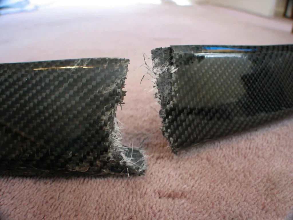
Variability and defects in current methods affect safety and reliability. High porosity thresholds (~2%) drive high component rejection rates.
Alternative 01
Prepreg autoclave curing
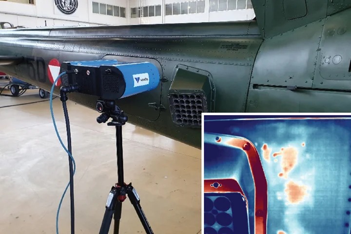
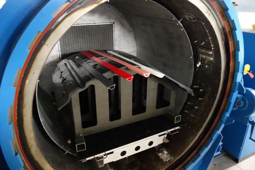
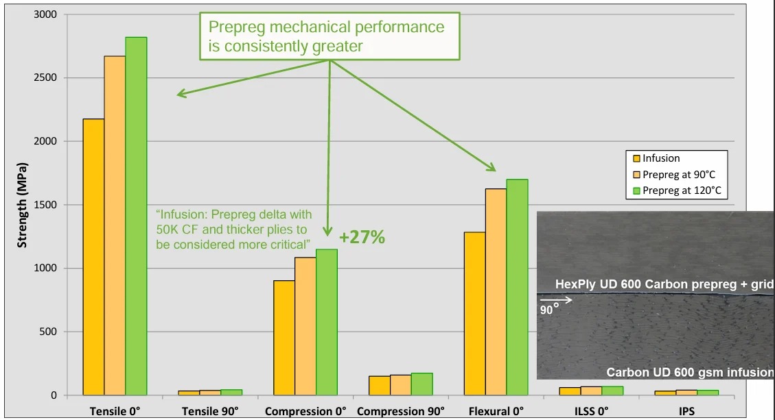
Heat and pressure cure pre-impregnated fibres, giving optimal resin distribution and minimal defects. Controlled resin content for higher strength and more consistent structures. Higher fibre volume fraction leading to roughly 10–12% better stiffness.
Alternative 02
Resin transfer molding (RTM)
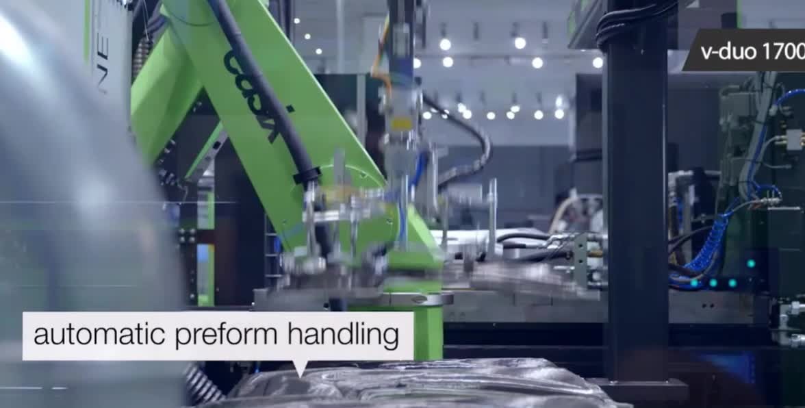
Low-viscosity resin is injected into a closed mold containing a fibre preform. High fibre volume fraction and fewer voids, increasing durability.
Alternative 03
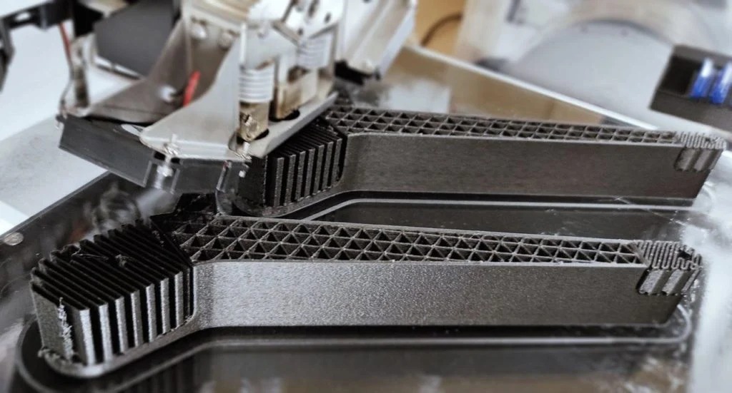
Carbon-fibre 3D printing
Continuous-fibre reinforcement deposited during 3D printing. Design flexibility with high strength and reduced material wastage. This alternative mainly focuses on continuous-fibre printing; its applications for manufacturing skin composites are very limited.
04 / Comparison & recommendations
Matching each failure to a process
Setup cost
Manufacturing cost
Labour
Flexibility
Surface finish
Strength
| Component | Observed failure | Recommended method | Why it works |
|---|---|---|---|
| UAV wing skins & empennage | Delamination, resin-rich zones (HLU) | Prepreg | Precise resin content; strong, light load-bearing skins |
| Lavatory panels & overhead bins | Surface waviness, fastener cracking (HLU) | RTM | Clean finish, mold-controlled geometry, lower rejection |
| C-17 landing-gear door panel | Dry spots, incomplete wet-out (VI) | Prepreg | Full impregnation, consistent quality at stiffener intersections |
| Wind-turbine blade roots | Voids, early fatigue failure (HLU/VI) | RTM or prepreg | RTM scales with compaction; prepreg maximises fatigue strength |
| Prototypes, small empennage & lavatory fittings | Delamination, resin-rich zones (HLU) | CF 3D printing | Fast prototyping, complex geometry, low tooling cost |
Table 04-02 — Recommended manufacturing method for each failure case.