DA/EngineeringProject / 03
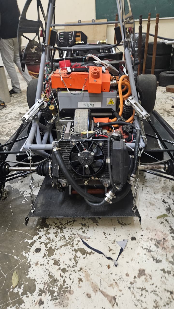
Prototype electric race car with the motor, radiator, coolant hoses, and high-voltage battery visible
Back to projects

Project 03

Electric Motor Cooling Circuit

A transient MATLAB Simulink and Simscape thermal-management model used a representative race-cycle load to identify the minimum radiator configuration capable of maintaining acceptable motor and motor-controller temperatures.

Project overview

Transient, race-cycle radiator sizing

The radiator was sized using a transient thermal-management model rather than a single steady-state operating condition. The model reproduced the electric powertrain response over a representative lap, coupled the resulting motor and controller heat loads to the liquid-cooling circuit, and enabled the radiator to be reduced iteratively to the minimum effective configuration.
01 / Duty cycle

A realistic transient load

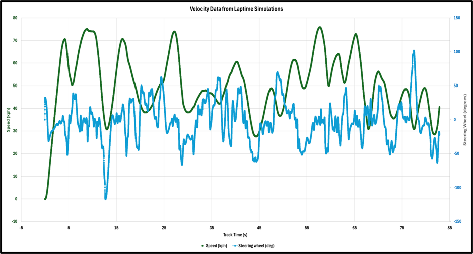
Motor demand was driven by lap-time simulation data rather than a single design point. The resulting time history formed the input for powertrain response and heat-generation calculations.

Lap-time simulation plot of vehicle speed and steering-wheel angle over track time
Representative lap-time input: vehicle speed and steering-wheel angle over the simulated duty cycle.

02 / Model development

From motor response to coolant heat rejection

Built a transient Simulink/Simscape model of the cooling circuit, driven by the time-varying motor power profile from lap-time simulation data to represent a realistic race-cycle load. Derived motor and inverter heat loads from the motor's efficiency-versus-power graphs — all efficiency losses treated as heat absorbed by the coolant — with a custom PI current controller reproducing the EMRAX 228 MV transient response. Modelled the radiator with the Simscape Simple Heat Exchanger and estimated coolant-side heat transfer using a Nusselt-number correlation.

Monitored motor inlet and other critical coolant and component temperatures across each transient simulation. Iteratively reduced the radiator size until the minimum configuration maintaining acceptable motor and controller temperatures was identified, rejecting approximately 1.4 kW.

03 / System architecture

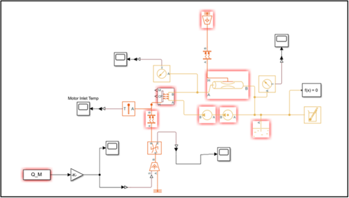
Coupled thermal-fluid circuit

MATLAB Simscape block model of the electric motor liquid-cooling circuit
Simscape thermal-fluid circuit with heat sources, circulation, resistance, sensing, and heat-exchanger elements.
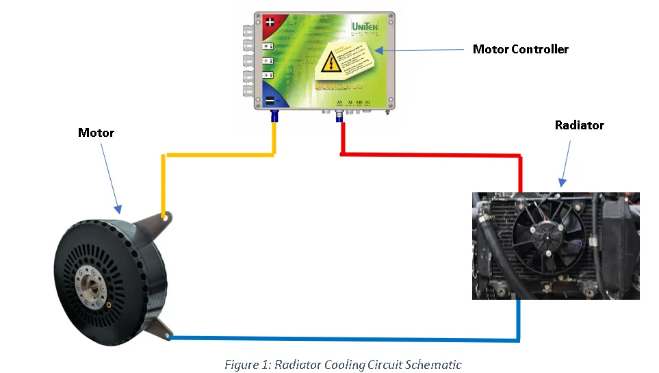
Cooling circuit schematic connecting the motor, motor controller, and radiator
System architecture linking the motor and controller heat loads to the radiator loop.

04 / Results

Minimum viable radiator configuration

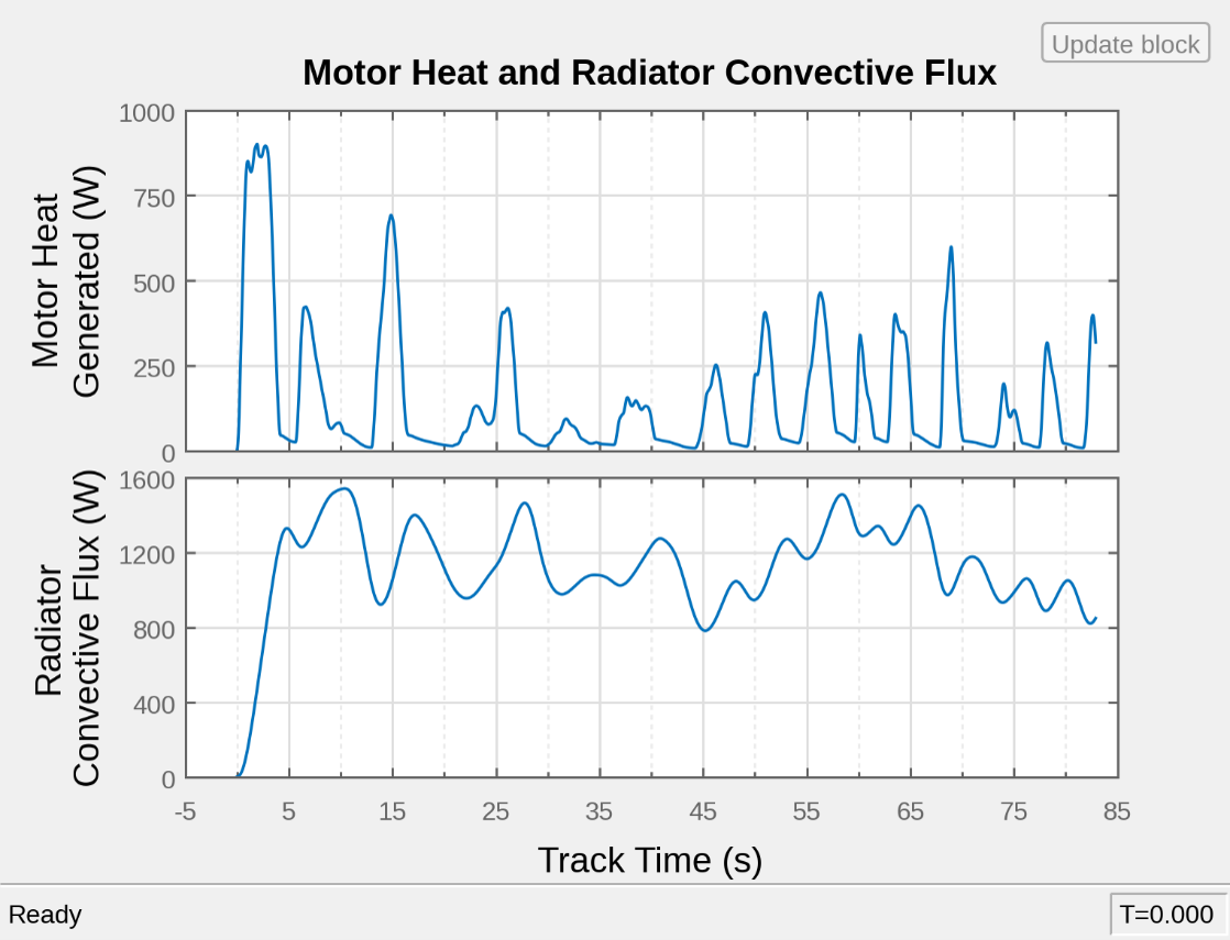
Repeated transient runs were used to reduce the effective radiator size while monitoring motor inlet and other critical temperatures. The final configuration maintained acceptable thermal behaviour and rejected approximately 1.4 kW from the combined motor and motor-controller loop.

Transient plots of motor heat generation and radiator convective heat flux
Transient motor heat generation and radiator convective heat rejection across the representative lap.
Design itemImplemented methodOutcome
Duty cycleLap-time power profileTransient race-load evaluation
Heat sourcesMotor and controller lossesCombined cooling-loop load
Radiator modelSimple Heat Exchanger with Nusselt correlationIteratively minimized effective size
Verified heat rejectionTransient thermal simulationApproximately 1.4 kW

05 / Prototype

Vehicle integration

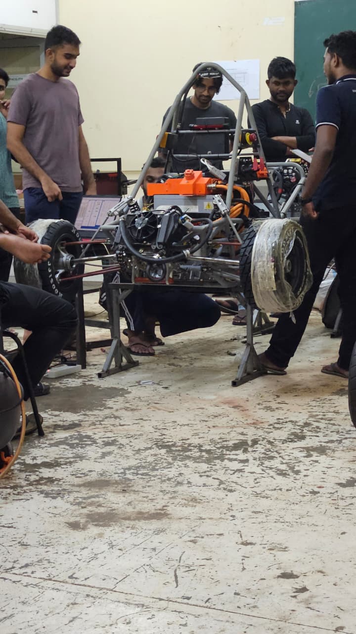
Team members working around the prototype electric race car during assembly
Prototype integration and cooling-system installation during workshop development.