DA/EngineeringProject / 02
Translucent stamped battery cold-plate model showing the serpentine coolant channel
Back to projects

Project 02

EV Battery Cold Plate Design

Steady-state conjugate heat-transfer CFD of a U-shaped serpentine liquid cold plate. The model transferred 340.04 W at 0.04 kg/s coolant flow and was compared with Guo and Li (2022).

Project overview

Serpentine-channel thermal validation

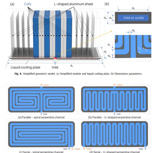
A three-dimensional steady-state CFD study of a single U-shaped serpentine liquid cold plate, adapted from the parallel-spiral serpentine channel work of Guo and Li (2022). The model resolved coolant flow and conjugate heat transfer through the plate, checked mesh independence and numerical convergence, then compared heat transfer, pressure drop and maximum temperature with the published study. Battery-cell thermal mass and cell dynamics were excluded: heat generation was represented as a uniform heat flux applied to the plate.
01 / Thermal model

Cell heating and flow assumptions

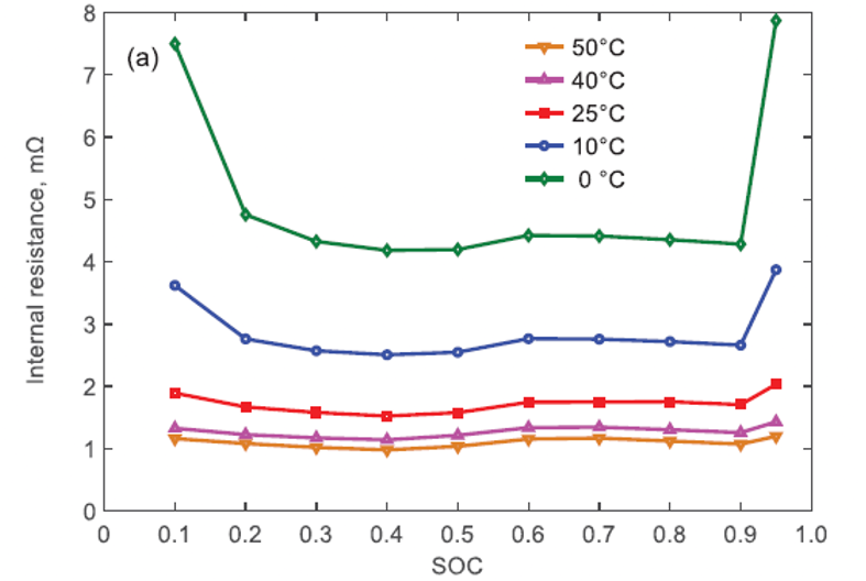
Modelled 16 cells at 1 C (50 A) with 9 mΩ equivalent internal resistance per cell near maximum state of charge. Joule heating, n × I²R, gives 360 W over 0.107304 m² of plate area: 3,354.95 W/m² imposed surface heat flux. Used 50% ethylene-glycol coolant with fixed properties over the narrow temperature range; inlet mass flow was prescribed, outlet pressure set to 0 Pa, walls made no-slip, and initial cell/ambient/inlet temperature set to 298 K. External walls were treated as insulated.

Restricted the 3D domain to the aluminium cooling plate and coolant passages, excluding battery cells. A steady-state approach follows the reference study's fixed flow and heat-load conditions; it does not represent transient driving cycles. Resolved turbulent channel flow with the standard k–ε model; used a least-squares cell-based gradient calculation and second-order upwind convective fluxes. Sharp bends remain a modelling sensitivity.

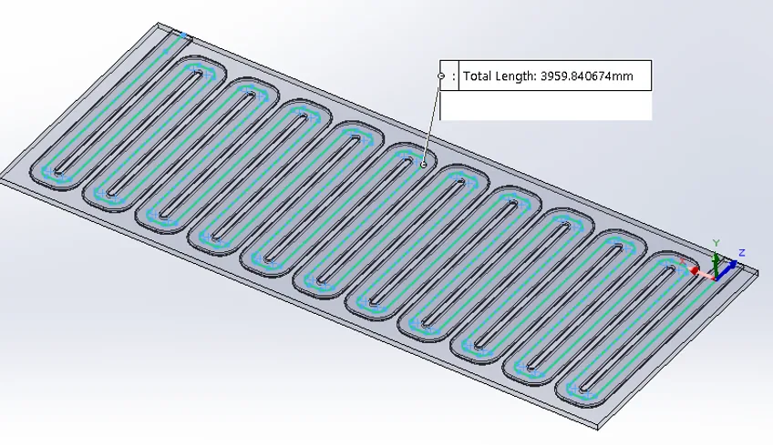
Dimensions of cold-plate geometries from Guo and Li 2022
Design and dimensioning of the cold-plate configurations simulated. Source: Guo and Li (2022).
Translucent stamped cold plate with coolant passage in blue
Translucent geometry model of the stamped cold plate, with the fluid path highlighted in blue.
Plot showing internal resistance of a cell versus state of charge
Variation of cell internal resistance with state of charge used to establish the Joule-heating input.

02 / Meshing & convergence

Resolving the serpentine channel

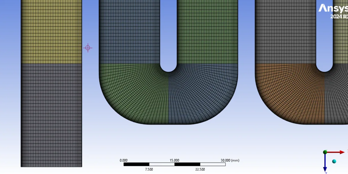
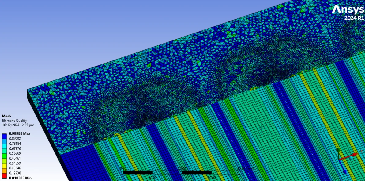
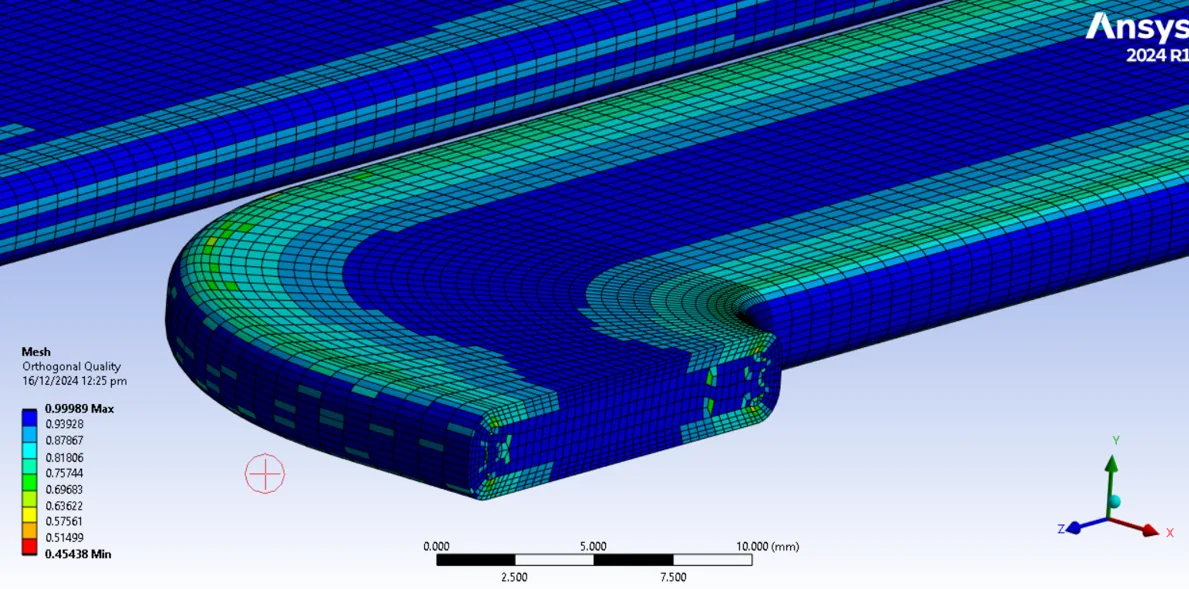
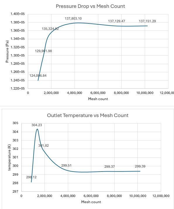
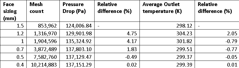
Sectioned the geometry with virtual/shared topology to form sweepable coolant passages with structured channel meshes; the more complex exterior combined hexahedral and tetrahedral elements. Applied face sizing to propagate mesh density through the fluid domain and examined orthogonality and near-wall resolution. The calculated first-layer height was 0.156 mm. A grid-independence study found results settling beyond roughly 7 million elements; the selected 0.5 mm face sizing produced 7,582,760 elements.

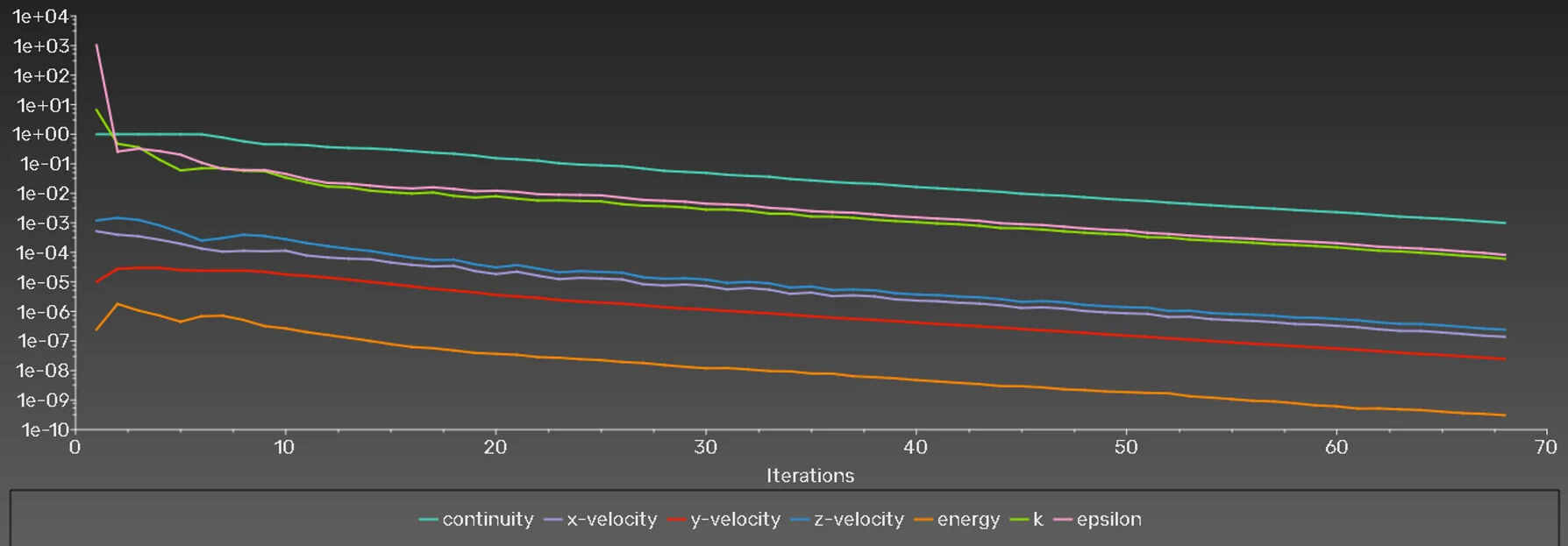
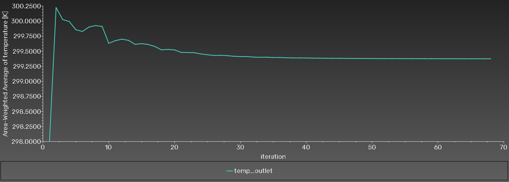
Tracked scaled residuals and outlet temperature for convergence. A reported 0.08 kg/s, 1 C case reached acceptable residuals in 68 iterations, taking approximately 50 minutes (about 44 seconds per iteration).

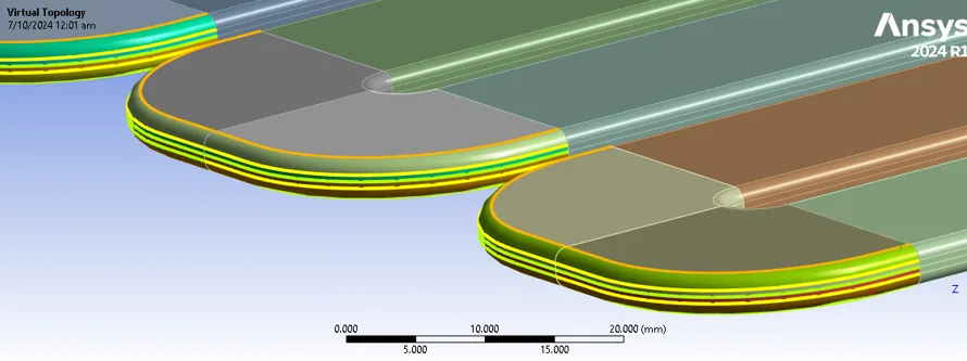
ANSYS sectioning and virtual-topology operations
Sectioning and virtual topology in ANSYS Meshing used to create sweepable, structured regions.
Structured mesh of serpentine coolant channel sections
Structured mesh of coolant-channel sections.
Mixed hexahedral and tetrahedral exterior plate mesh
Exterior cold-plate mesh combining hexahedral and tetrahedral elements around complex geometry.
Section view showing orthogonal quality of cold-plate mesh
Orthogonal mesh quality displayed alongside a section view.
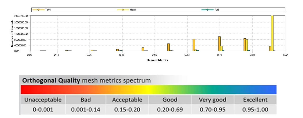
Distribution of element orthogonality in the mesh
Orthogonality distribution of mesh elements.
Grid-independence plots for pressure drop and outlet temperature
Mesh-independence plots for pressure drop and outlet temperature as element count increases.
Mesh-independence study result table
Mesh-independence study results used to select the 7,582,760-element mesh.
Scaled-residual convergence plot
Convergence plot of scaled solver residuals.
Convergence plot of cold-plate outlet temperature
Outlet-temperature convergence across solver iterations.

03 / Results & validation

Comparing with Guo and Li (2022)

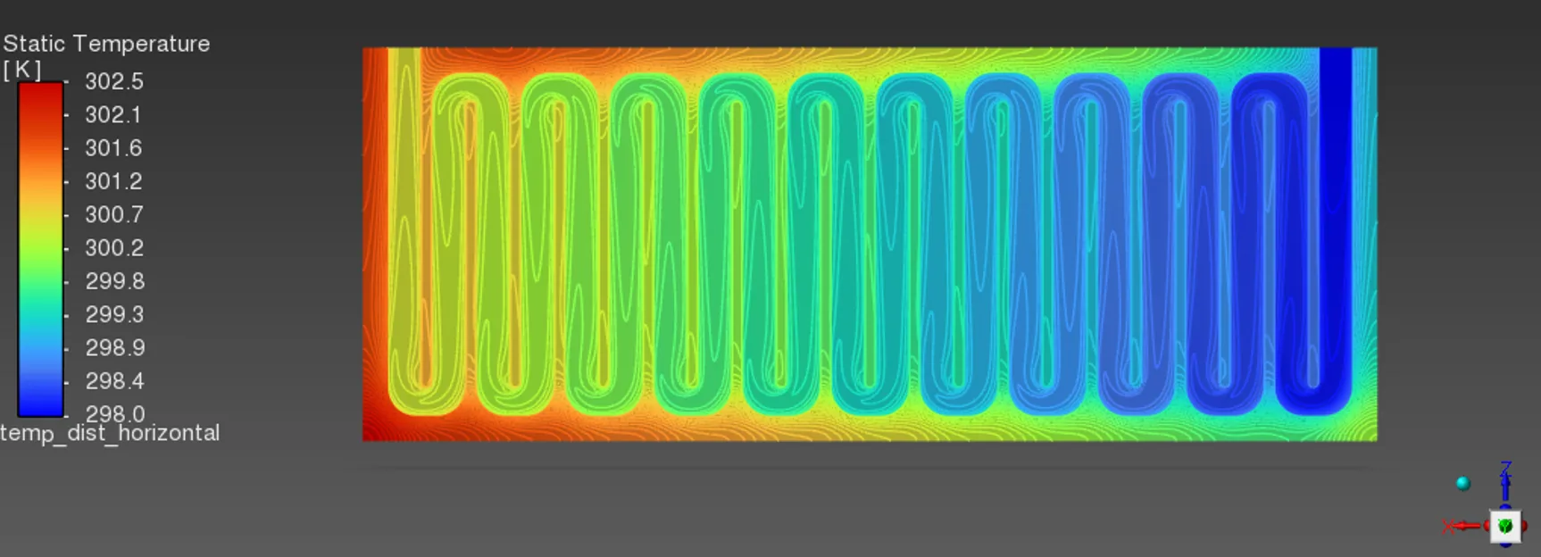
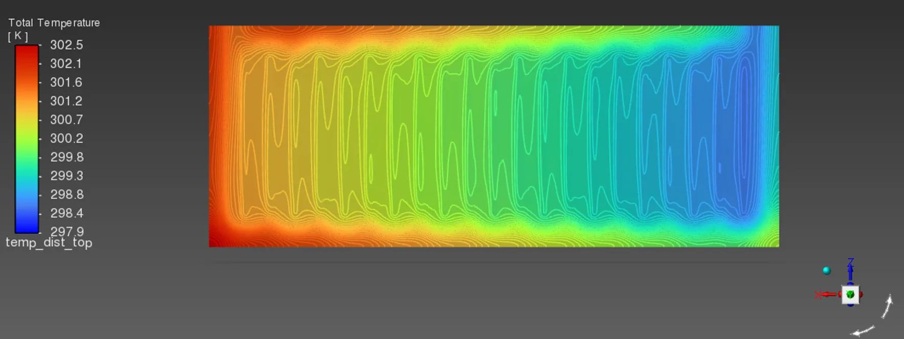
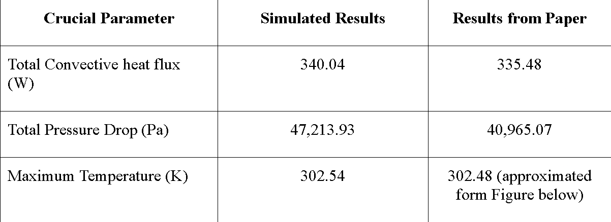
At 0.04 kg/s and 1 C, the simulated total convective heat transfer was 340.04 W versus 335.48 W in Guo and Li (2022). Maximum temperature was 302.54 K versus approximately 302.48 K in the reference; the midplane ranged from 297.95 to 302.53 K and the contact surface from 297.98 to 302.532 K. Pressure drop was 47,213.93 Pa versus 40,965.07 Pa in the reference. The report attributes the difference to finer resolution of eddy losses at the serpentine bends; that explanation is a modelling interpretation, not an experimentally verified cause.

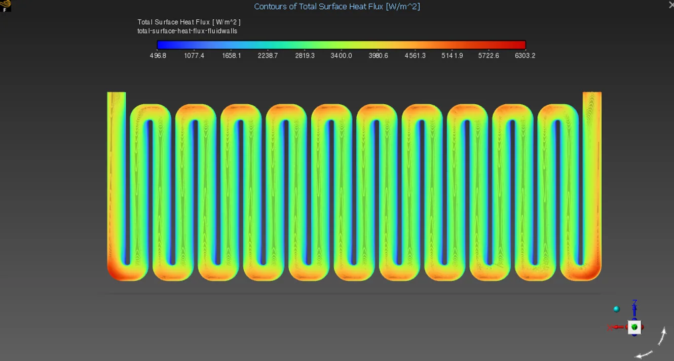
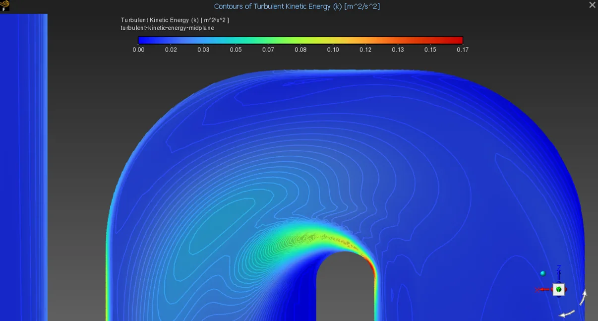
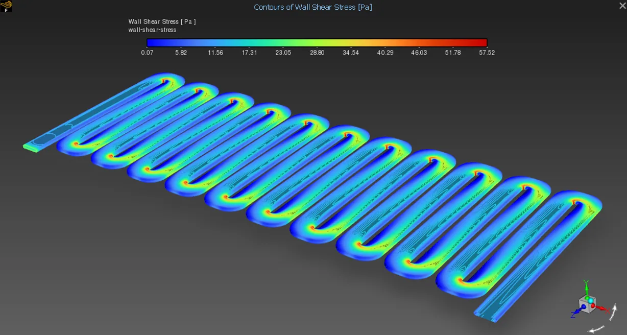
Wall shear stress ranged from 0.0706 to 57.5216 Pa and local surface heat flux from 496.78 to 6,303.19 W/m². Turbulent-kinetic-energy and shear-stress contours suggest separation near inner bends.

Parameter · 0.04 kg/s, 1 CThis simulationGuo and Li (2022)
Convective heat transfer340.04 W335.48 W
Total pressure drop47,213.93 Pa40,965.07 Pa
Maximum temperature302.54 K≈302.48 K

Table 03-01 — Simulated cold-plate results compared with the values reported by Guo and Li (2022); reference maximum temperature is approximated from a published figure.

Temperature contours across cold-plate midplane
Temperature distribution contours across the midplane.
Temperature contours on cell-contact surface
Temperature distribution contours across the contact surface of the cold plate.
Surface heat-flux contours on fluid domain walls
Distribution of surface heat flux along the outer walls of the fluid domain.
Turbulent kinetic energy along serpentine channel
Turbulent kinetic energy along the fluid channel, suggesting flow separation at inner bends.
Wall shear stress distribution along channel walls
Wall shear stress along the fluid-channel walls, also suggesting separation near inner bends.
Table comparing simulated results with the reference study
Comparison of simulated results with Guo and Li (2022).

04 / Limitations

Next validation steps

Uniform cell heat flux, constant coolant properties and a steady-state solution simplify real battery operation; no cell thermal mass, spatially varying heating or transient cell dynamics were included. Standard k–ε with wall functions and second-order upwind discretization may miss fine eddies and smear sharp gradients near bends. Future studies could test k–ω SST or LES, variable heat loads and transient operation. The 7.58-million-element mesh is computationally expensive; targeted adaptive refinement near bends and thermal gradients could reduce cost before further validation.