DA/EngineeringProject / 04
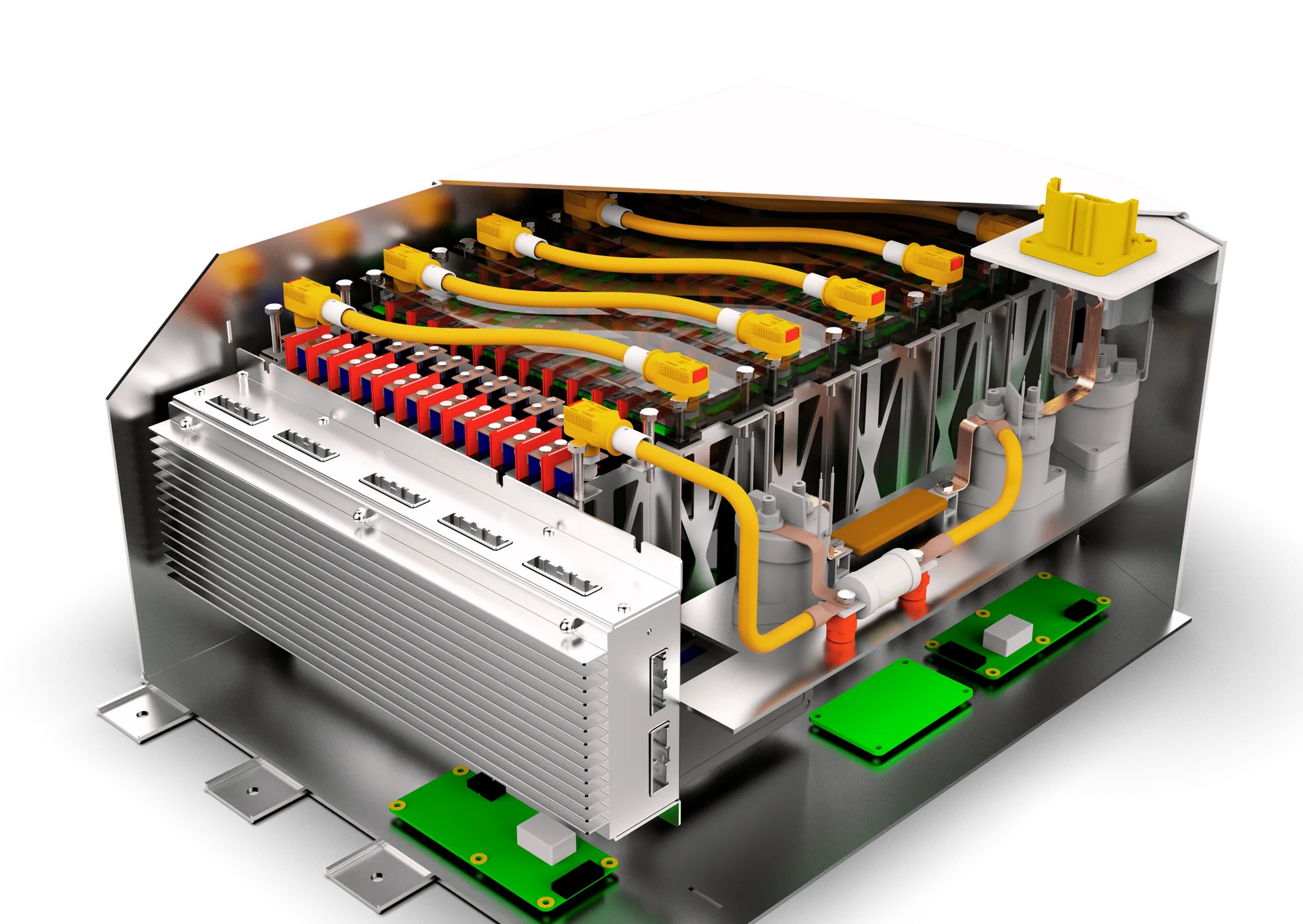
Sectioned 600 V Formula Student battery pack rendering showing the cells, segments, casing and electrical connections
Back to projects

Project 04

600V Battery Pack

Mechanical design of FalconE Racing’s pouch-cell accumulator: segment packaging, aluminium containment, impact-load analysis, chassis mounting and cooling provisions for a Formula Student EV.

Project overview

A segmented, impact-analysed accumulator

The accumulator mechanical design brings 144 pouch cells into a compact, segmented high-voltage pack. The work covers a lighter aluminium enclosure, cell restraint and fire barriers, Formula Student impact-load calculations and structural simulations, mounting interfaces, and preliminary cooling design. Figures and values below are design calculations and simulated results, not physical test certification.
01 / Architecture

Pouch-cell packaging and mass

Replaced 72 Enepaq Energus modules (46.224 kg) with 144 × 14 Ah pouch cells (40.032 kg in the mass comparison), saving 6.192 kg at cell/module level. Used a conservative estimated accumulator mass of 72 kg for structural loading, down from a 78 kg steel-walled predecessor; the new casing uses aluminium walls and base, so the estimate retains margin rather than claiming a measured final mass. Packaged the cells in 24-cell segments with monitoring PCBs, connectors and fasteners; the pack envelope shown in the design is 615.77 × 414.00 × 268.01 mm.

Developed the enclosure, removable lid, segment partitioning and battery-to-chassis packaging as a coordinated mechanical assembly.

Cutaway rendering of the complete battery assembly
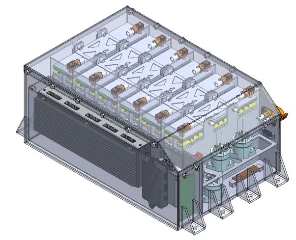
Sectioned pack rendering showing the arrangement of cells, partitions, conductors and housing.
Transparent battery enclosure showing internal cell segments
Translucent enclosure view reveals segment layout and internal packaging.
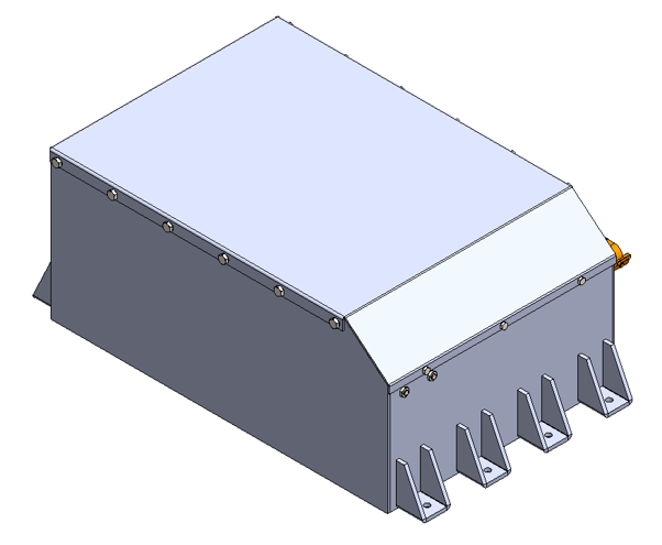
External CAD model of the battery enclosure
External casing geometry and chassis-mounting feet.
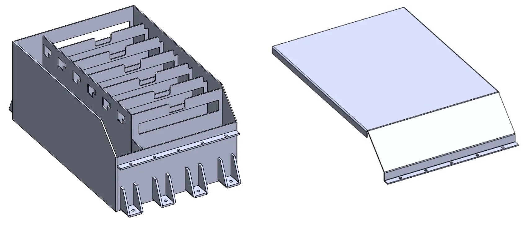
Separated battery casing and lid
Enclosure and removable lid shown separately.
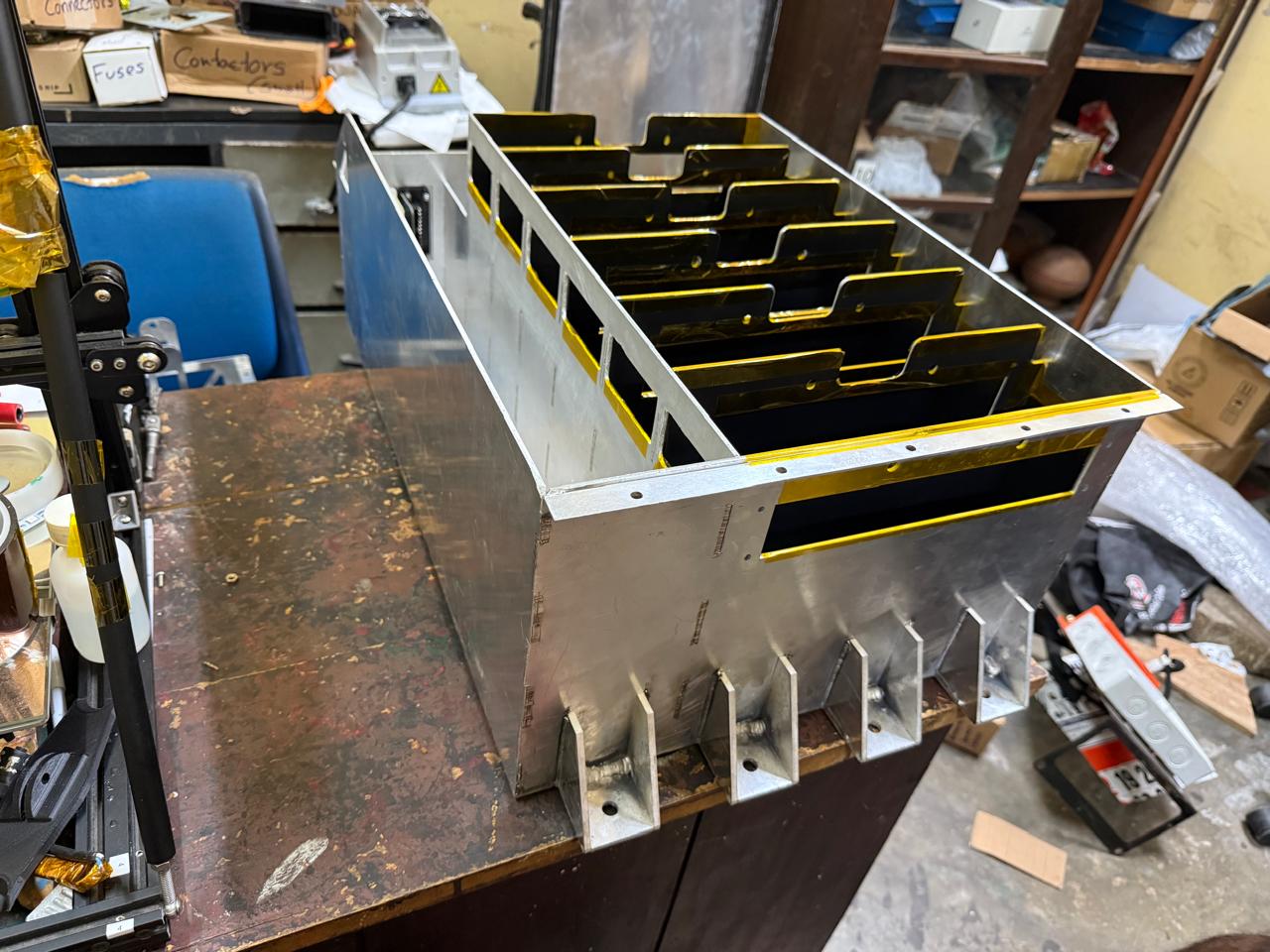
Photograph of the manufactured aluminium battery casing
Manufactured battery casing.
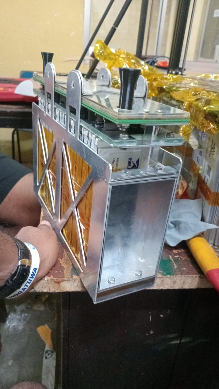
Photograph of the manufactured battery segment casing
Manufactured battery segment casing.
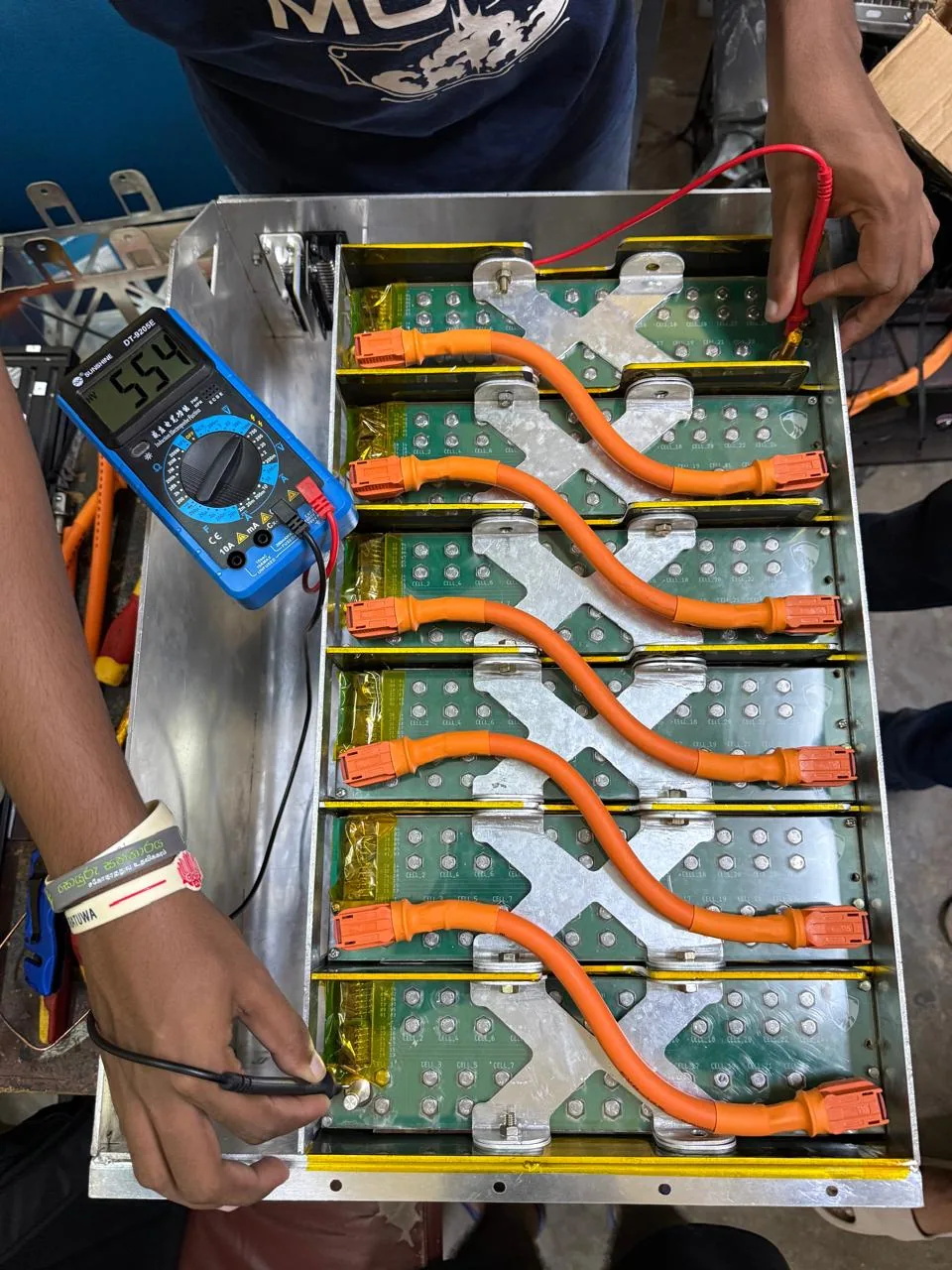
Photograph of the first series connection of all battery cells
First series connection of all battery cells.
Design measureBaseline / inputPack design
Cell/module mass72 modules · 46.224 kg144 pouch cells · 40.032 kg
Estimated accumulator mass78 kg steel-walled72 kg conservative structural input
Pack envelope—615.77 × 414.00 × 268.01 mm

Table 01-01 — Mass comparison, conservative load assumption and CAD envelope from the design document.

02 / Vehicle integration

Making space within the chassis

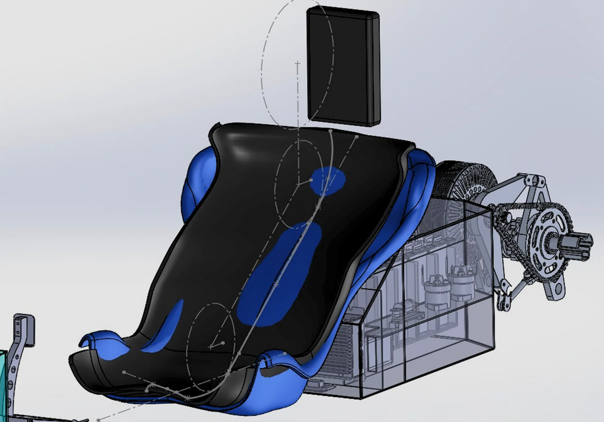
Battery packaging relative to the Formula Student chassis and driver
Vehicle packaging study around the driver, chassis and accumulator envelope.
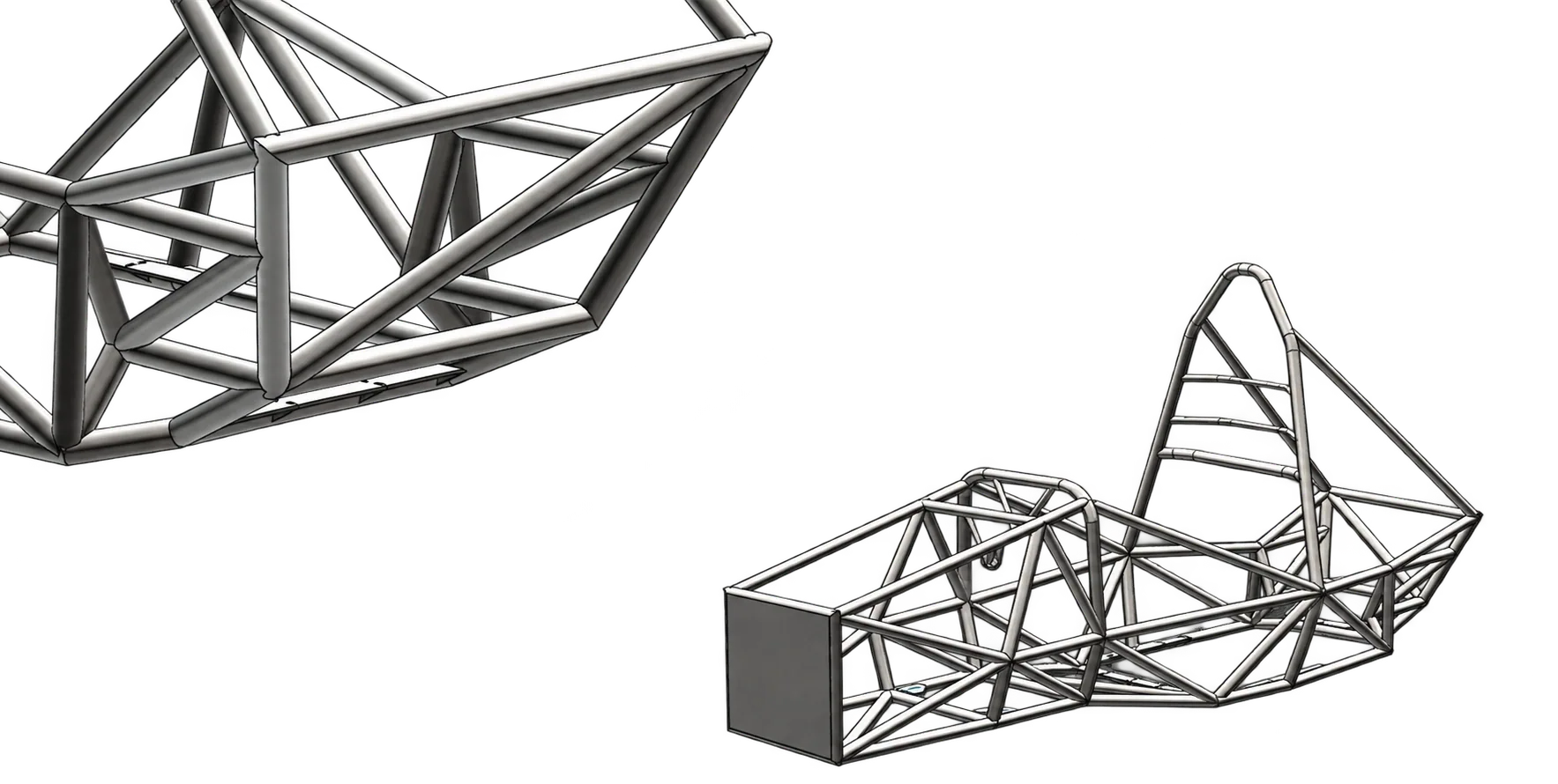
CAD of the race car mechanical chassis
Chassis design used to define the mounting and packaging interfaces.
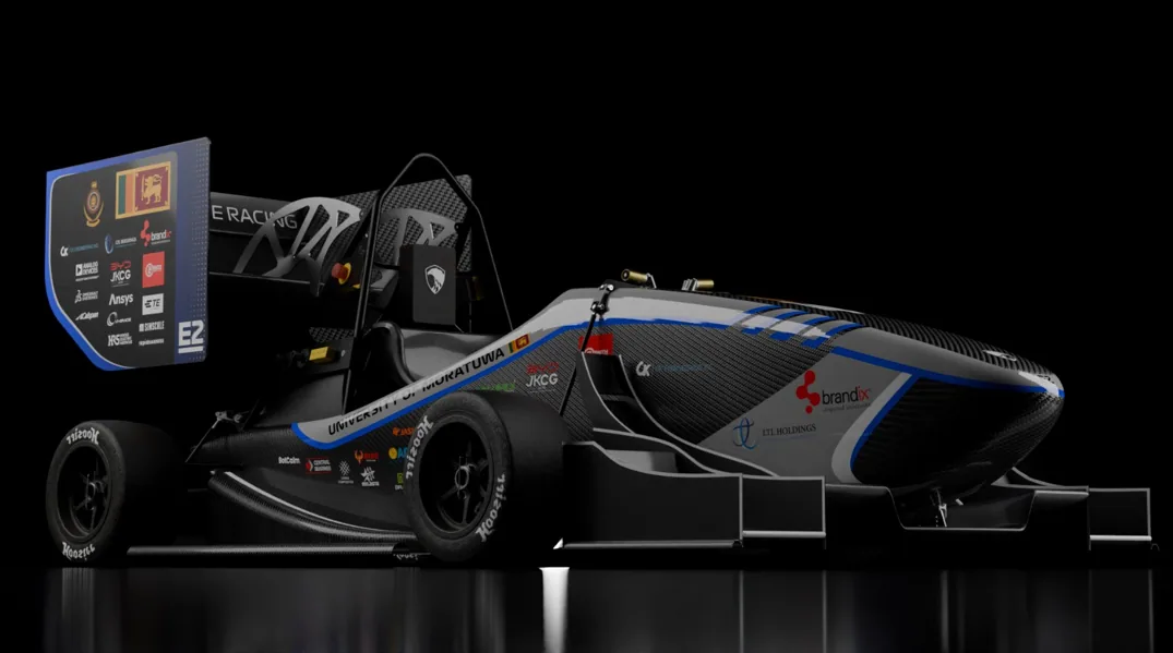
Rendering of the complete Formula Student electric race car
Vehicle-level context for the pack and chassis integration.

03 / Structural validation

Casing and segment under impact loads

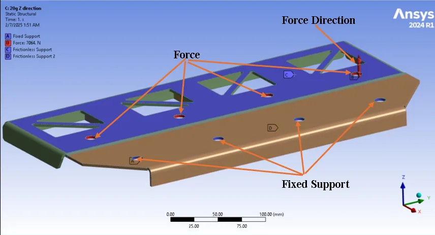
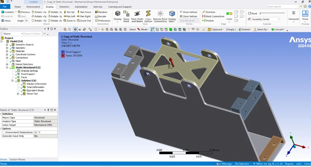
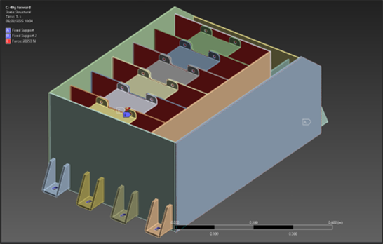
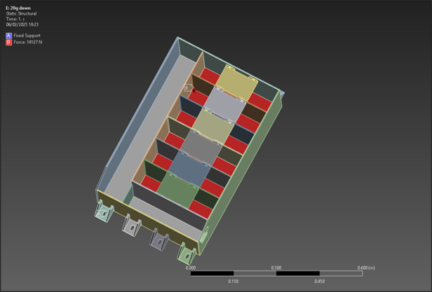
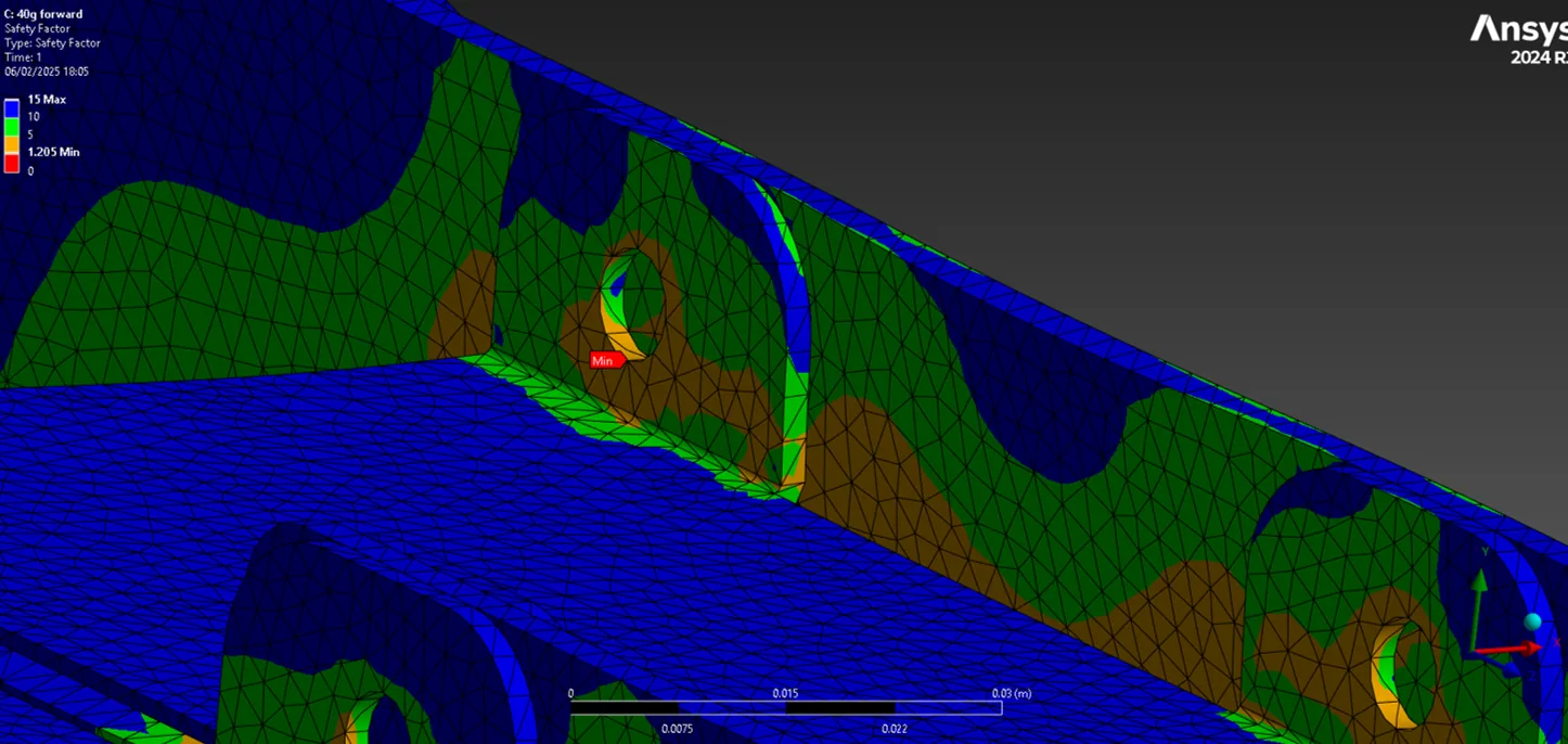
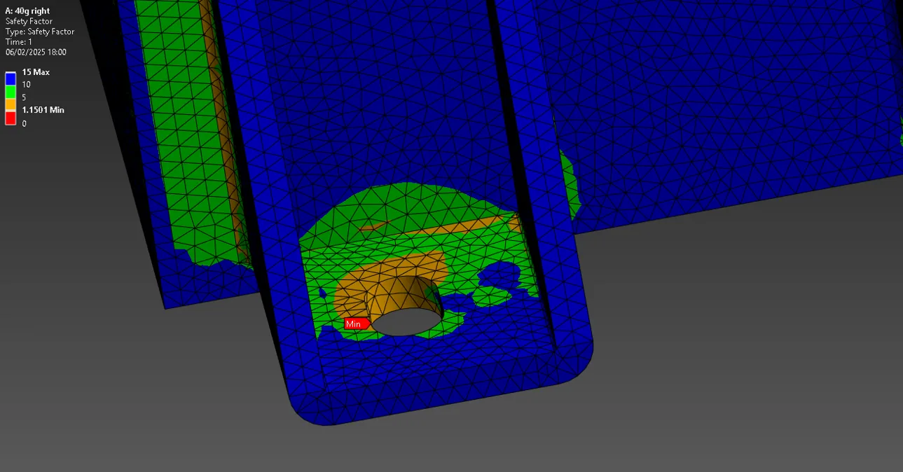
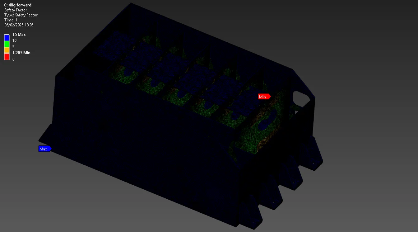
Applied FSUK 2025 T9.2 critical-component accelerations: 40g forward/rearward and left/right, and 20g up/down. At the conservative 72 kg design mass these correspond to 28,252.8 N and 14,126.4 N. Analysed the aluminium 6061-T6 casing and brackets across all six directions. Minimum simulated safety factors were 1.15 (right), 1.06 (left), 1.205 (forward), 1.304 (rearward/up) and 1.637 (down). Checked a 24-cell segment at 20g vertical acceleration using 7.168 kg dynamic mass (24 × 282 g cells plus 400 g PCB/connectors/fasteners): 1,406.36 N total and about 351.59 N per fastener, assuming four equal load paths.

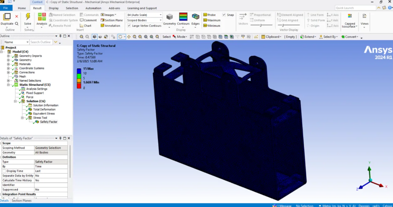
Selected M8 grade 8.8 segment bolts; calculated single-shear bolt stress of ~7 MPa and 3 mm aluminium segment-casing bearing/shear estimate of 4.65 MPa. The segment simulation returned a minimum safety factor of 1.6697.

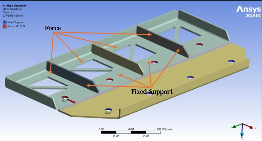
Battery segment longitudinal impact loading setup
Segment loading and supports for the longitudinal 40g case.
Battery segment vertical loading setup
Segment loading and supports for the vertical case.
ANSYS segment impact-loading simulation setup
Segment geometry and applied impact-loading boundary conditions.
Simulated safety-factor distribution in a battery cell segment
ANSYS segment safety-factor distribution; minimum reported value 1.6697.
Battery casing longitudinal force distribution
Longitudinal casing-load distribution used in the structural analysis.
Battery casing vertical force distribution
Vertical casing-load distribution used in the structural analysis.
Local stress in the battery casing under longitudinal loading
Casing stress concentration under 40g longitudinal loading.
Local stress in the battery casing under lateral loading
Casing stress concentration under 40g lateral loading.
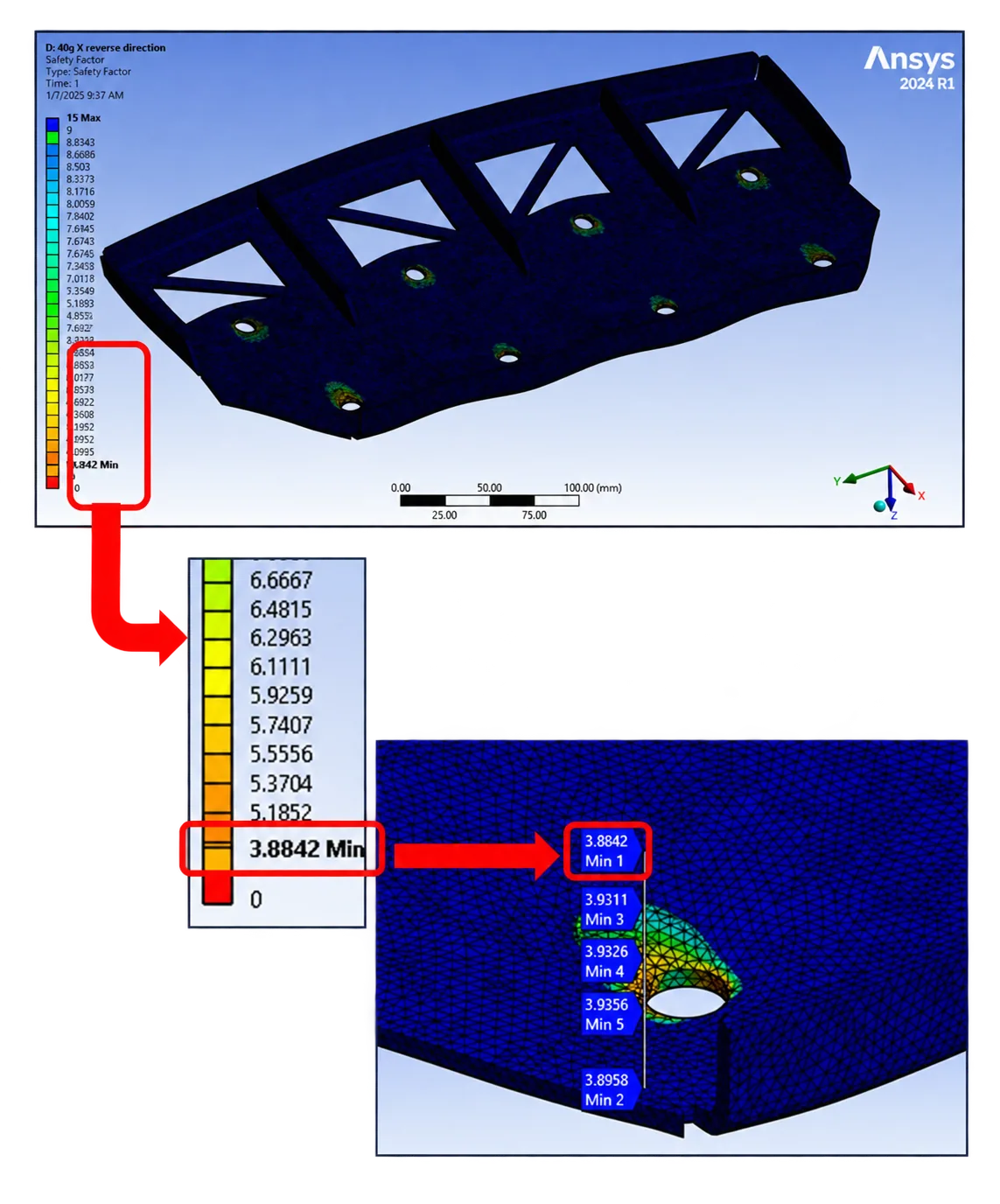
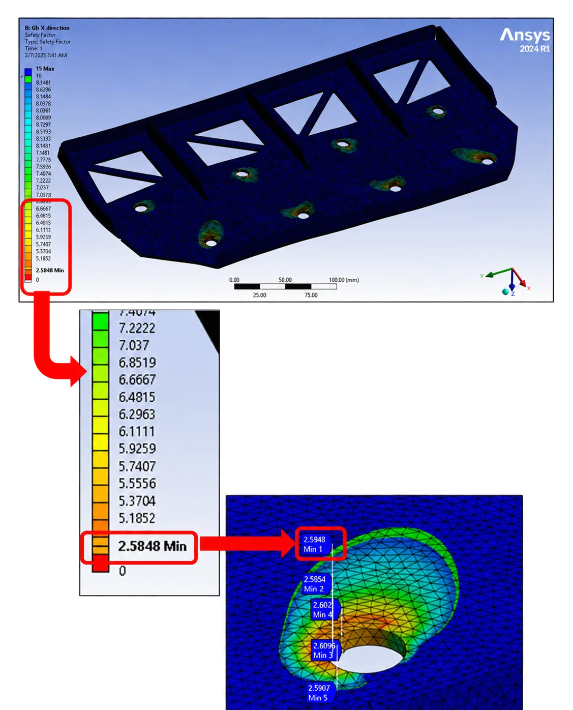
Casing safety-factor contour under 40g longitudinal loading
Casing safety-factor distribution for the longitudinal loading case.
Casing load caseMinimum simulated safety factor
40g right1.15
40g left1.06
40g forward1.205
40g rearward1.304
20g upward1.304
20g downward1.637

Table 03-01 — Minimum safety factors reported for the aluminium 6061-T6 casing and brackets in the design analysis.

04 / Mounting

Load path into the frame

Distributed the 72 kg accumulator load across eight mounting bolts in the hand calculation: 3,531.6 N shear per bolt at 40g and 1,765.8 N tension per bolt at 20g. Selected M10 grade 8.8 mounting bolts; calculated ~44.97 MPa single-shear stress per bolt against a 320 MPa assumed allowable (640 MPa yield / factor of 2). Calculated ~46.84 MPa bracket shear in 6 mm aluminium 6061-T6 against a 155 MPa assumed allowable (310 MPa yield / factor of 2). Structural load paths were also investigated by simulation.

Battery mounting bracket simulation under longitudinal load
Mounting-bracket simulation under 40g longitudinal loading.
Battery mounting bracket simulation under lateral load
Mounting-bracket simulation under 40g lateral loading.

05 / Thermal protection

Cell barriers and cooling provisions

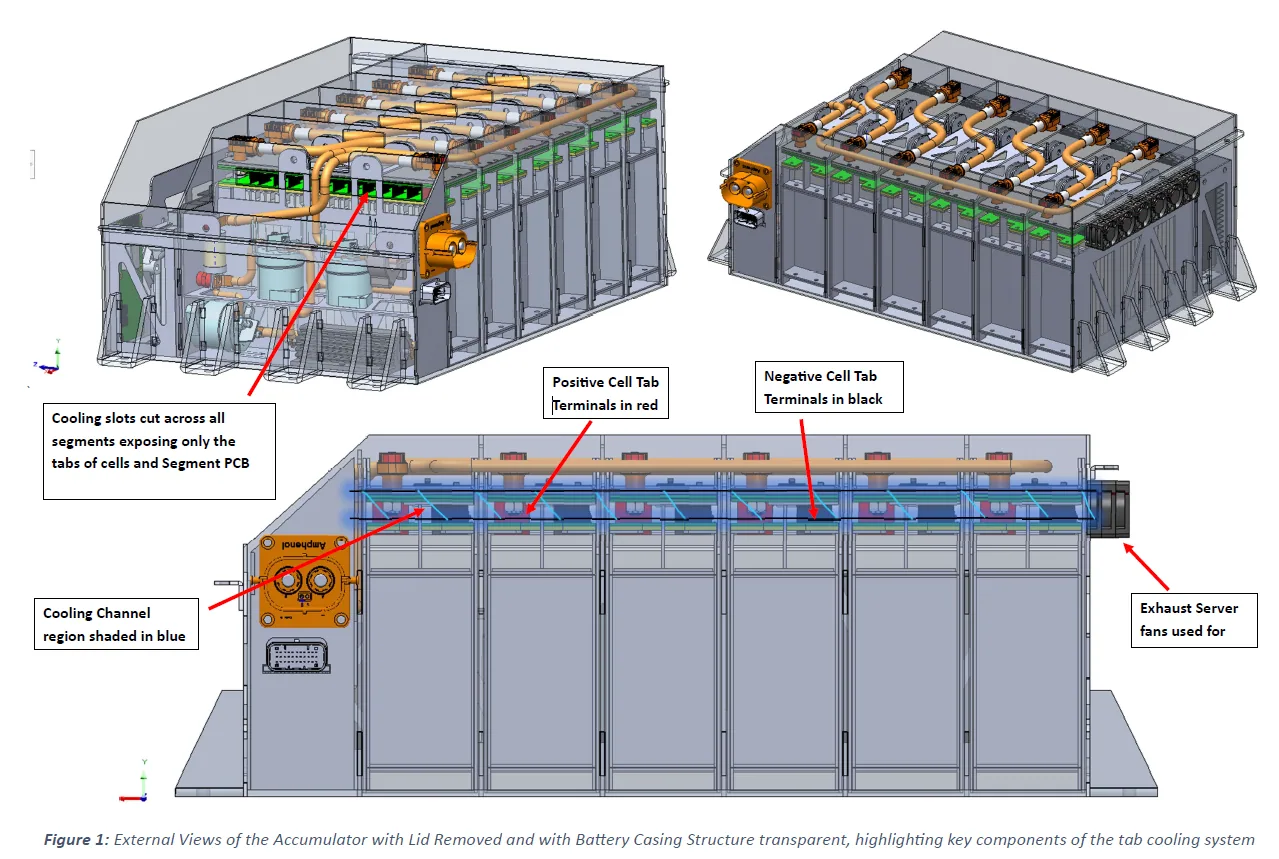
Enclosed pouch-cell tops and sides with 3 mm UL94-V0-rated, electrically insulating FR4 sheets, allowing only paired cell tabs through narrow slots; additional FR4 separates adjacent segments and caps each segment. Separated segments with 3 mm aluminium walls extending to the accumulator lid. Openings occupying about 7% of each wall expose tabs and cell-monitoring PCBs to an air channel exhausted by low-voltage-powered server fans.

The preliminary thermal worksheet uses a 600 V pack, 80 kW maximum draw, 133.33 A pack current and 35.56 W heat generation per cell, yielding a 5,120 W full-pack heat-load estimate. These are sizing assumptions, not measured rejection. The same worksheet separately explores aluminium-plate/water-cooling calculations: a 1.74 °C cell-to-water temperature difference and 0.70 kg/s required coolant flow at a separate 1.74 °C coolant temperature rise for 5,120 W. This is an explored estimate, not evidence that the pictured air-cooled layout incorporates a water circuit.

Annotated battery air-cooling design showing cells, FR4 insulation and air passages
Proposed insulated segment architecture and forced-air passage across exposed cell tabs and monitoring PCBs.
Sizing inputWorksheet value
Pack voltage / peak power600 V / 80 kW
Peak pack current133.33 A
Estimated heat per cell35.56 W
Estimated pack heat load5,120 W
Water-loop study (separate calculation)0.70 kg/s at 1.74 °C coolant rise

Table 05-01 — Preliminary thermal sizing calculations; the forced-air layout and water-loop worksheet are distinct concepts.