DA/EngineeringProject / 07
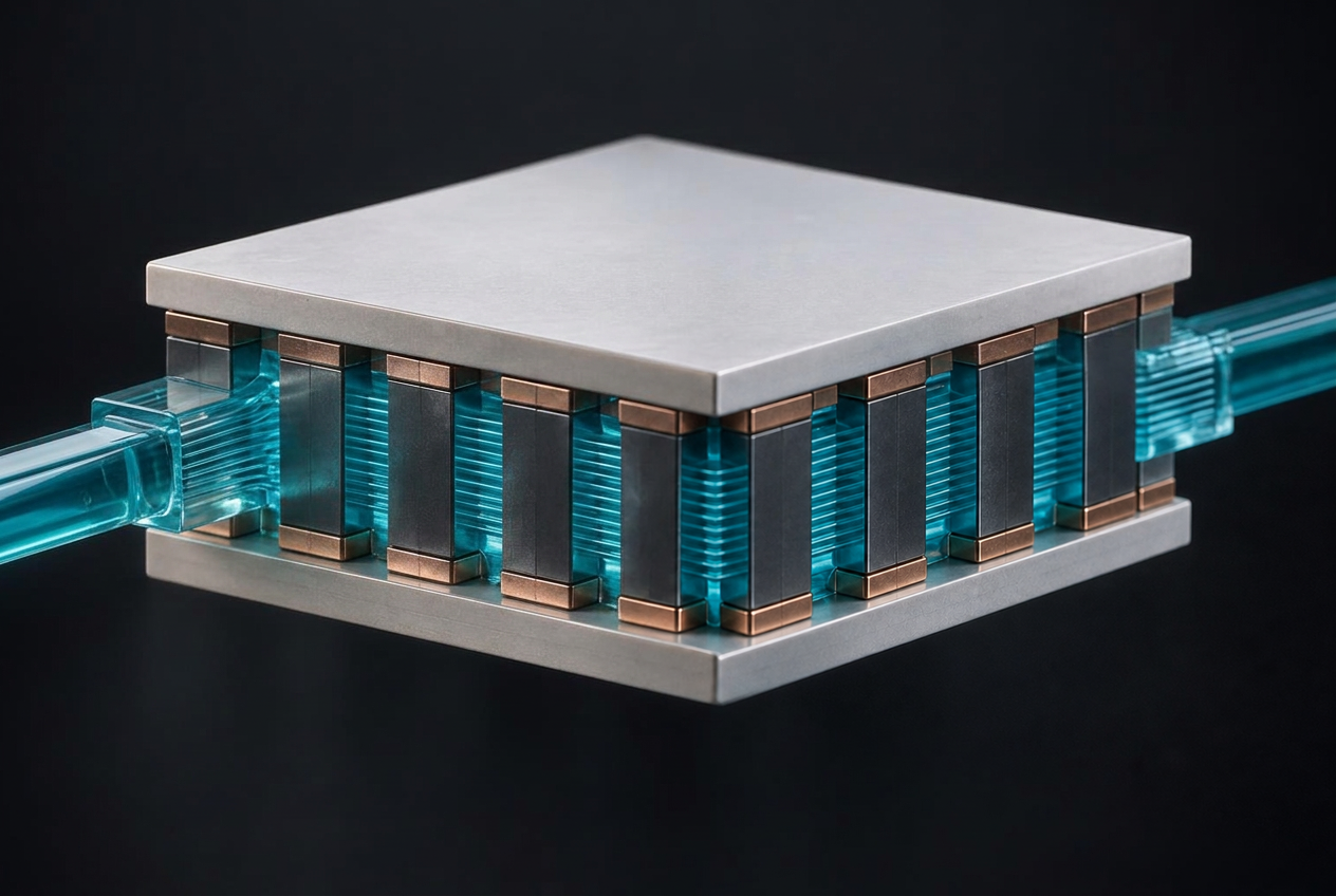
Concept illustration of an integrated liquid-cooled thermoelectric module with a left inlet and rear-right outlet
Back to projects

Project 07

Integrated Microchannel Thermoelectric Cooler

A compact cooling concept that routes liquid between thermoelectric legs instead of attaching an external cold plate. A COMSOL multiphysics comparison found up to 57.9% higher simulated COP than a conventional configuration under favorable operating conditions. Research accepted for IEEE IECON 2026.

Project overview

Cooling within the module

Compact processors and power devices need localized cooling without the bulk of a separate heat sink. This research routes coolant through all the spaces between thermoelectric legs inside a sealed module, allowing convection alongside Peltier cooling. A conventional thermoelectric cooler with an external straight-fin microchannel plate served as the numerical baseline.

01 / Architecture

Coolant inside the thermoelectric module

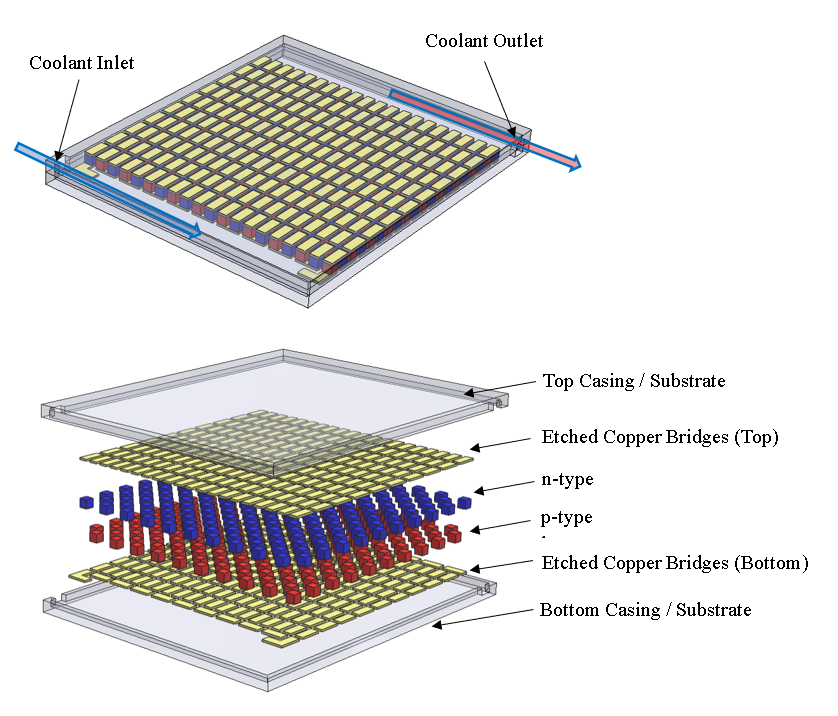
The proposed ceramic-enclosed assembly places the coolant path between the thermoelectric legs rather than in a separate hot-side cold plate; liquid enters one face and leaves the opposite face. The paper describes 40 bismuth-telluride legs per unit (20 p–n pairs), with 1.5 mm square legs and 0.72 mm inter-leg channels. Ten units form an approximately 46 × 46 × 4 mm assembly; this remains a proposed design, not a fabricated prototype.

Paper schematic of the enclosed thermoelectric assembly, inter-leg coolant paths and exploded p-type and n-type legs
Figure 01 — Proposed integrated microchannel TEC architecture and inter-leg coolant pathway (from the research paper).

02 / Numerical method

A matched comparison with a conventional cooler

Coupled laminar flow, conjugate heat transfer and thermoelectric effects in steady-state COMSOL Multiphysics models of the integrated (G1) and conventional (G2) layouts. Ran 80 simulated cases across two cooling-surface temperatures (293.15 and 313.15 K), four voltages (0.05–0.5 V) and five Reynolds numbers (100–2000), under matched conditions. Checked mesh independence to below 1% change in cooling flux and compared the model with published numerical results from Ruan et al.; cooling power and COP differed by 2.2% and 2.9%, respectively.

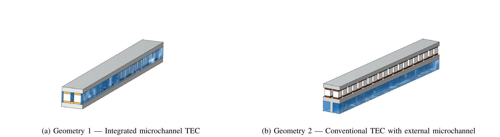
Paper comparison of integrated thermoelectric model and conventional thermoelectric module with external cold plate
Figure 02 — COMSOL model geometries: integrated inter-leg flow (G1) versus external microchannel cold plate (G2).
Validation measurePublished referencePresent modelDeviation
Cooling power0.45 W0.44 W2.2%
COP0.600.582.9%

Table 02-01 — Numerical model comparison against Ruan et al. as reported in Table IV of the paper; not experimental validation of the proposed hardware.

03 / Findings

Efficiency gains with a cooling-capacity trade-off

57.9%Peak simulated COP gain
22–26%Less simulated Joule heating
20.9%Up to 20.9% lower electrical power
>50%Estimated form-factor reduction

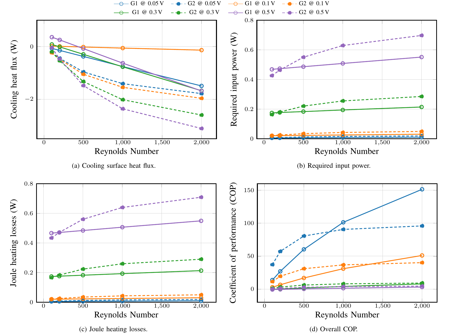
At 0.05 V and Re = 2000, simulated COP reached 151.42 for the integrated layout versus 95.87 for the conventional layout: a 57.9% improvement at that operating point. At 0.5 V and Re = 2000, simulated electrical input was 0.551 W versus 0.697 W (20.9% less); Joule-heating losses were around 22–26% lower over moderate-to-high cooling loads. The paper estimates more than 50% less overall cooling-system form factor by eliminating the separate cold plate. This is a packaging estimate, not a prototype measurement.

The trade-off matters: at 0.05 V and Re = 1000, the conventional design absorbed 1.411 W at the cooling surface versus 0.760 W for the integrated design; higher COP does not always mean more instantaneous cooling.
Four paper plots comparing cooling flux, input power, Joule losses and COP across Reynolds numbers
Figure 03 — Simulated cooling flux, electrical input, Joule losses and COP against Reynolds number at four applied voltages. Solid lines: G1; dashed lines: G2.

04 / Research status

Accepted for IEEE IECON 2026

Results are numerical, not measurements from a fabricated cooler. The intended implementation calls for a dielectric-compatible fluid; the comparison simulations used a published-reference graphene-nanoplatelet nanofluid instead. Sealing, fluid compatibility and performance require experimental verification. At high voltage and low flow, Joule heating can overwhelm cooling; the COP advantage is strongest at low voltage and sufficiently high flow.

The cover image is a concept illustration, not a photograph or an exact representation of the simulated geometry. The diagrams and charts above are reproduced from the supplied research paper.