DA/EngineeringProject / 06
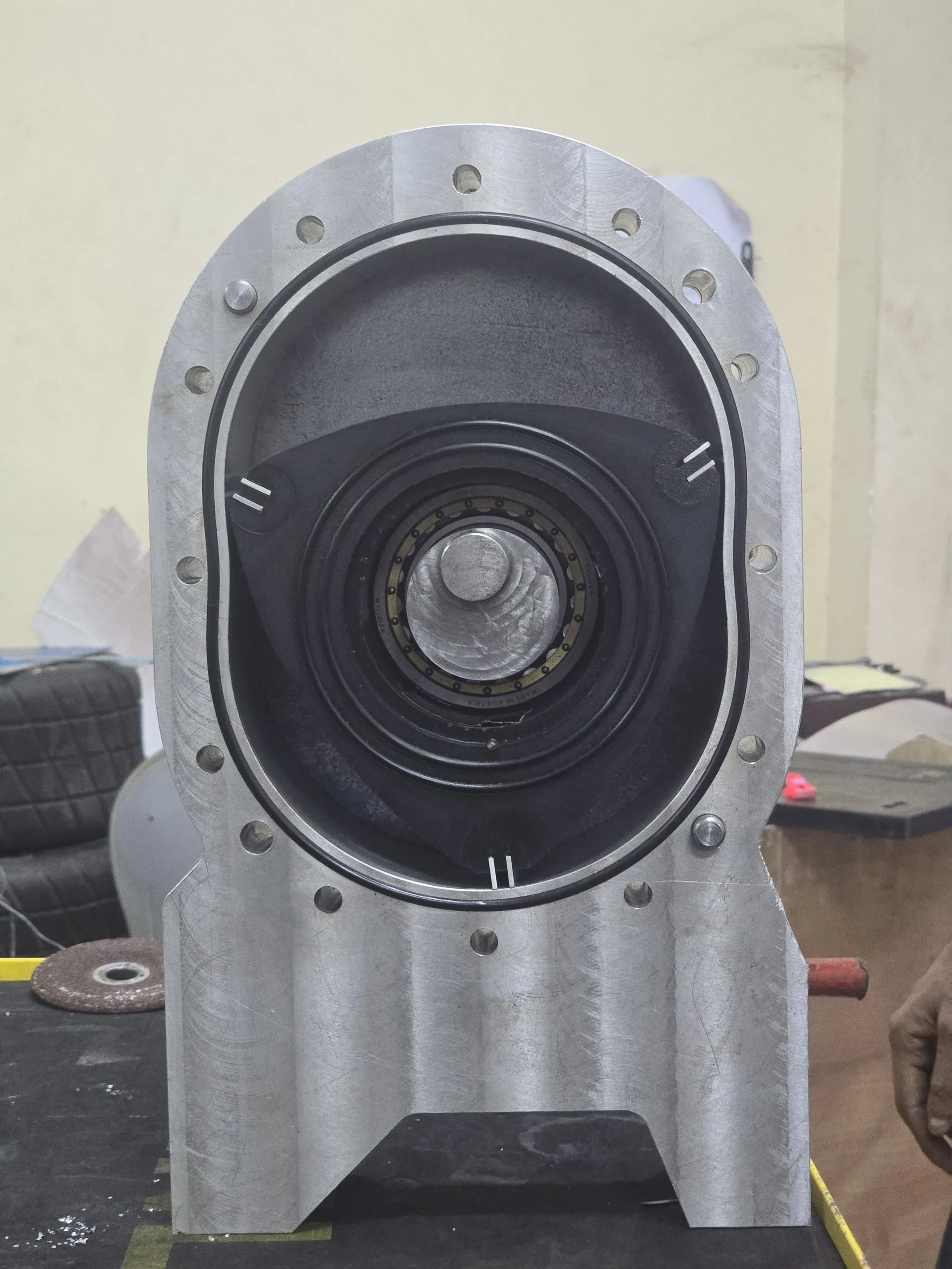
Constructed proof-of-concept Wankel rotary engine prototype
Back to projects

Project 06

Wankel Rotary Engine Lubrication System

Designed and validated a recoverable centrifugal lubrication system that routes oil through the Wankel rotor to the apex seals, then captures and recycles it to reduce the losses of conventional net-loss lubrication.

Project overview

Recoverable centrifugal apex-seal lubrication

Wankel engines offer compact geometry, smooth operation, and a high power-to-weight ratio, but conventional systems struggle with apex-seal lubrication, oil consumption, and emissions. This project developed a recoverable centrifugal system that uses rotor motion to deliver oil from the central cavity to each apex through internal channels. A new multi-piece seal then controls, scrapes, drains, and recirculates excess lubricant while preserving the required oil film.
01 / Design intent

Oil delivery, control, and recovery

Maintain a continuous lubricating film between each apex seal and the epitrochoidal housing. Recover excess lubricant instead of consuming it through a conventional net-loss oil-injection system. Improve sealing and lubrication without adding excessive mechanical complexity. Validate the concept through CFD, a crank-angle-resolved MATLAB model, and a physical prototype.

Conventional net-loss oil-injection lubrication used as the design baseline.
Wankel rotor motion and changing chamber geometry.
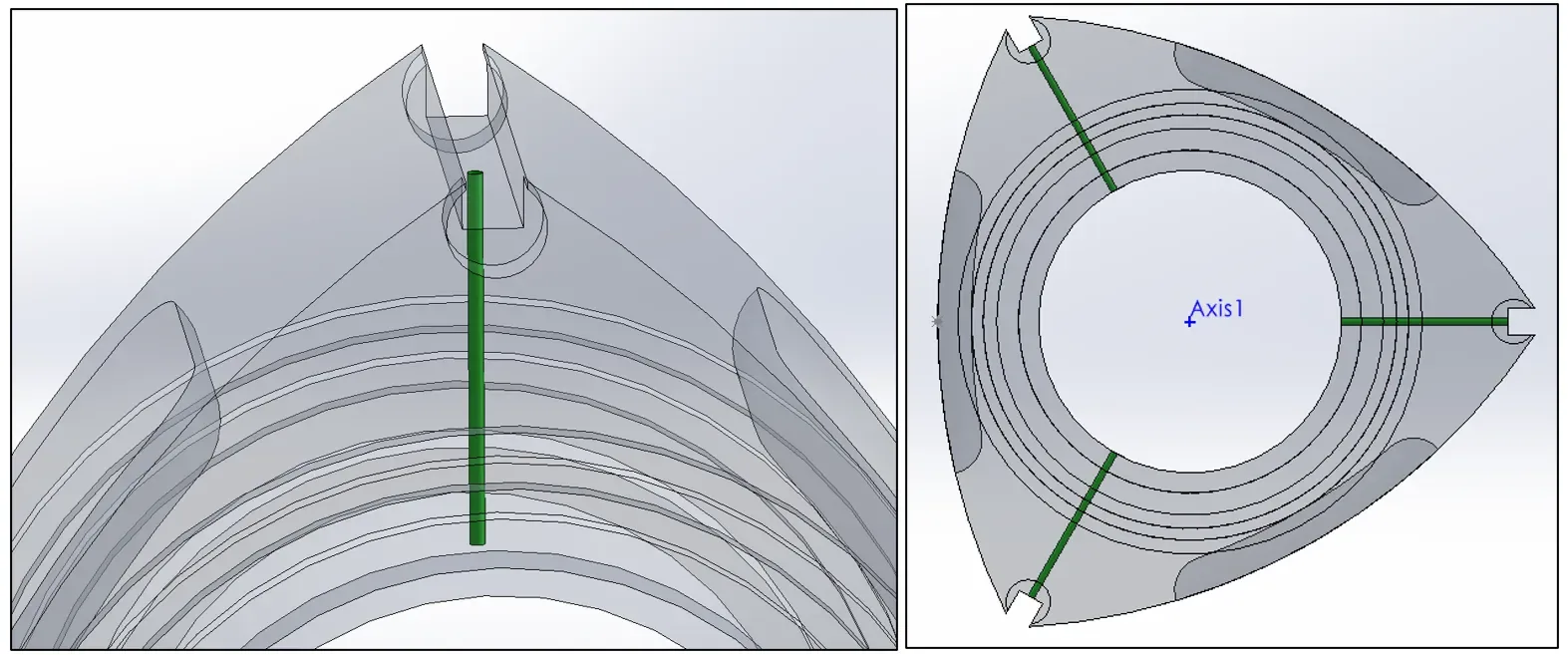
Novel lubrication channels highlighted in green through the Wankel rotor
Proposed internal channels route lubricant from the rotor cavity to all three apex regions.
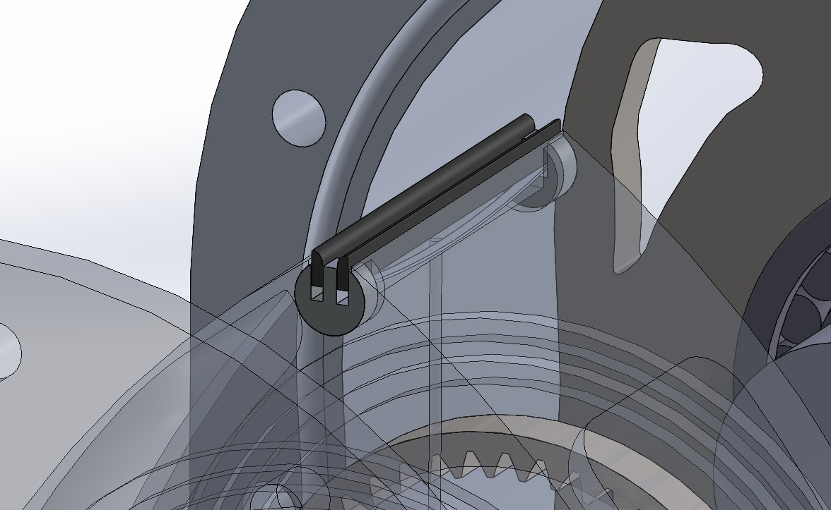
Dual apex-seal design compared with a conventional single apex seal
Dual apex-seal concept developed for oil control, scraping, drainage, and recovery.
Functional spring-loaded dual apex-seal mechanism.

02 / Numerical method

Multiphase CFD and analytical film model

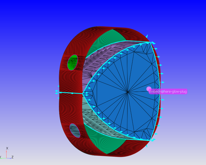
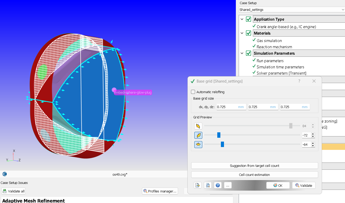
Modelled the rotor, housing, and lubrication channels in CONVERGE (OSF49-II) on a 251,140-cell Cartesian cut-cell mesh with adaptive refinement. Resolved oil–air flow with VOF multiphase, RNG k-ε turbulence, cavitation, surface tension, wall adhesion, and a deforming/regenerating mesh. Applied a rotor-motion user-defined function, no-slip walls, 0 MPa / 298 K boundaries, and a 23% initial oil mass fraction in the rotor cavity.

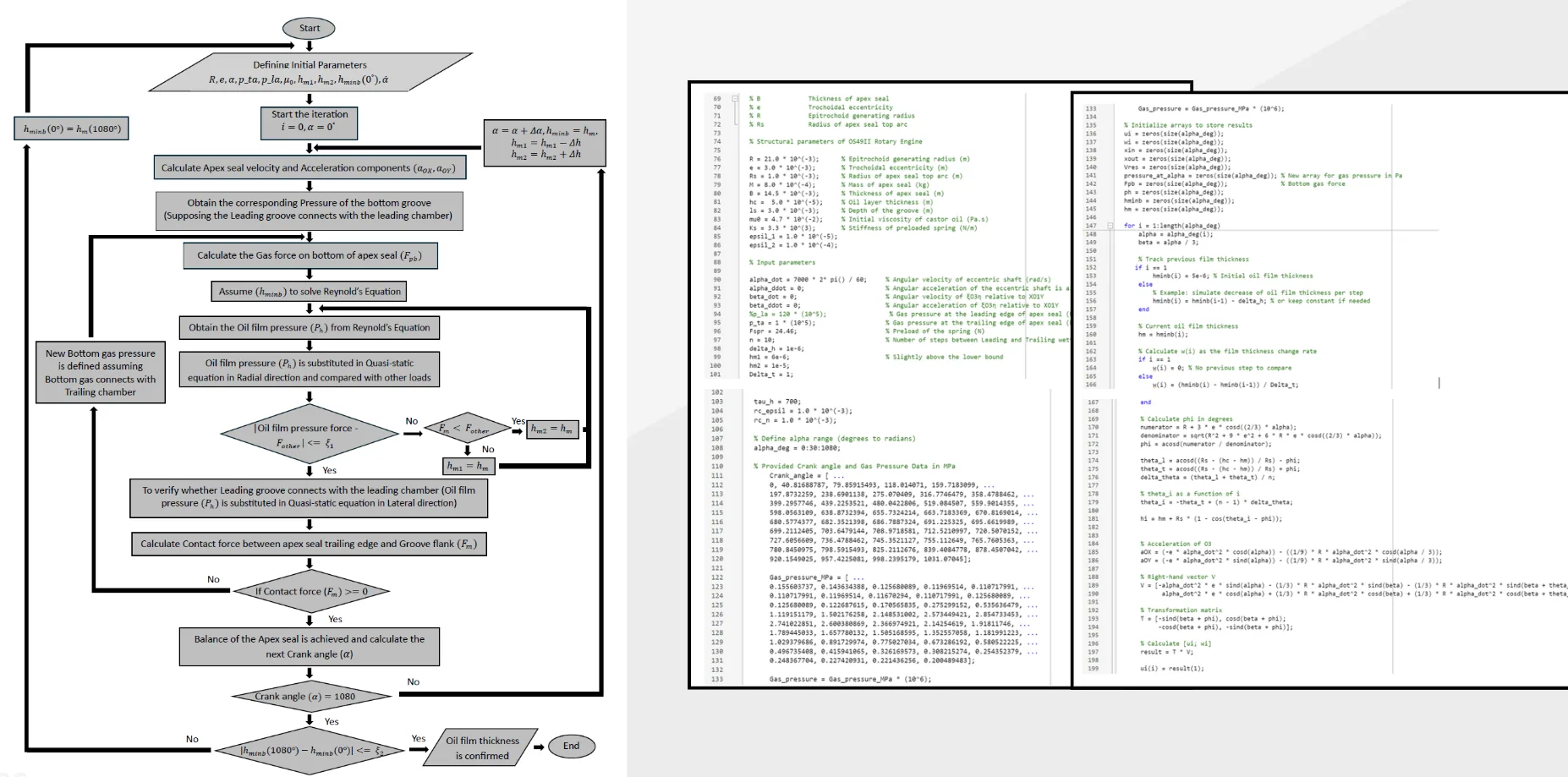
Drove an iterative MATLAB model with the CFD chamber pressure and temperature histories, solving seal kinematics, Reynolds lubrication pressure, force balance, contact force, and minimum film thickness from 0° to 1080°. Built a proof-of-concept prototype to assess mechanical feasibility, visible film formation, oil recovery, and the multi-piece seal arrangement.

Initial surface mesh of the Wankel rotor and housing geometry
Initial surface mesh defining the rotor, housing, chambers, and lubrication passages.
Base Cartesian CFD grid surrounding the Wankel geometry
Base grid before cut-cell generation and adaptive refinement.
MATLAB numerical model used to determine apex-seal lubrication thickness
Crank-angle-resolved MATLAB model coupling chamber conditions, seal forces, Reynolds pressure, and film thickness.
Model parameterValueModel parameterValue
Generating radius21 mmRotor eccentricity3 mm
Apex-seal radius1 mmApex-seal length14.5 mm
Initial mesh251,140 cellsInitial oil mass fraction23%
Boundary state0 MPa / 298 KWall roughness1.4 × 10⁻⁷ m
Analysis cycle0°–1080°Validation speed7,000 rpm

03 / Simulation inputs

Crank-angle-resolved chamber conditions

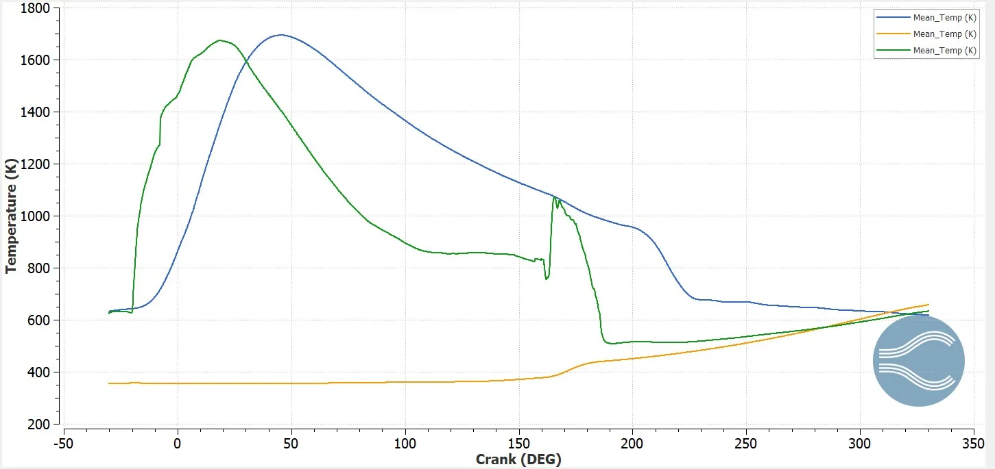
Mean temperature of each chamber plotted against crank angle
CFD-derived mean chamber-temperature histories used by the analytical lubrication model.
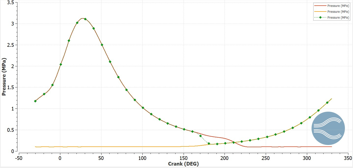
Mean pressure of each chamber plotted against crank angle
CFD-derived mean chamber-pressure histories used to calculate crank-angle-resolved film behaviour.
Simulated flame propagation — left chamber view.
Simulated flame propagation — right chamber view.
Transient temperature contour — left chamber view.
Transient temperature contour — right chamber view.
Transient pressure contour — left chamber view.
Transient pressure contour — right chamber view.

04 / Findings

Lubrication performance and validation

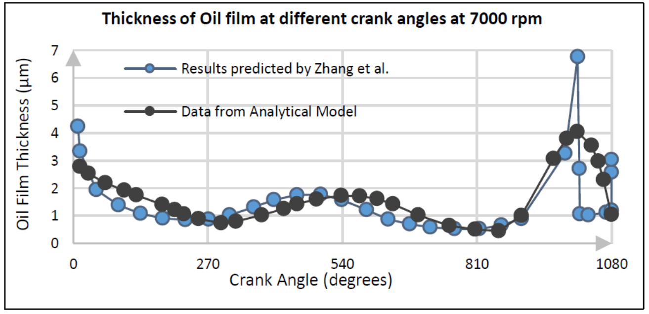
2D studies confirmed centrifugal transport of lubricant from the rotor cavity to all three apexes. At 7,000 rpm the analytical film trend reproduced the characteristic W-shaped curve reported by Zhang et al. Predicted film thickness matched reference values across most of the 1080° cycle — e.g. 4.2 μm vs 4.3 μm at 0° and 0.9 μm vs 1.0 μm at 180°. High calculated oil-film pressure showed a supporting film could be maintained under operating conditions. The scraper-and-drain multi-piece seal improved oil recovery in early tests, with promising reductions in oil loss.

All tested lubricants formed an adequate film; higher-viscosity grades held it more consistently than thinner oils.

Initial 2D result confirming centrifugal oil transport to the apex regions.
Oil-film thickness at different crank angles at 7000 rpm
Predicted oil-film thickness at selected crank angles at 7,000 rpm and the rotor-housing TDC position.
Crank anglePublished referenceAnalytical model
0°4.3 μm4.2 μm
90°2.2 μm2.1 μm
180°1.0 μm0.9 μm
360°1.5 μm1.4 μm
720°1.7 μm1.6 μm
1080°2.8 μm1.2 μm

Table 04-01 — Predicted apex-seal oil-film thickness versus the reference data reported by Zhang et al. at selected crank angles.

05 / Prototype

Physical concept verification

The prototype confirmed that the internal oil path and multi-piece seal arrangement were mechanically feasible. Tests with 5W-20, 15W-40, 20W-50, API-GL4, and API-GL5 lubricants all produced an identifiable oil film, while the more viscous oils maintained it more consistently.

Constructed proof-of-concept Wankel rotary engine prototype
Constructed prototype used to assess mechanical feasibility, film formation, and lubricant recovery.
Prototype test showing the lubrication concept in operation.
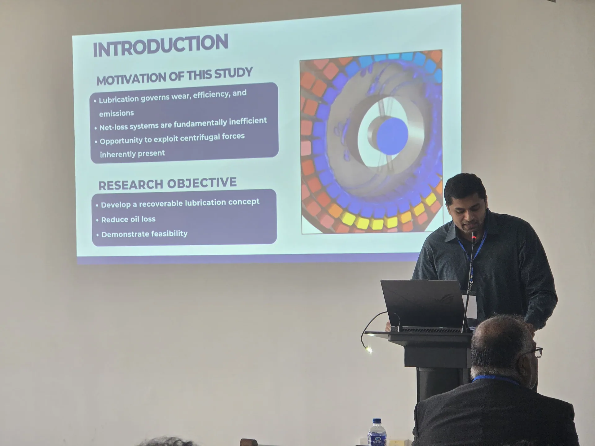
Dihan Amaratunga presenting the Wankel lubrication research at the Mechanical Engineering Research Symposium 2025
Presentation at the Mechanical Engineering Research Symposium 2025.

06 / Limitations & next steps

Path to operating-engine validation

Live oil-film thickness could not be measured, so the prototype provided qualitative proof of visible film formation rather than direct thickness validation. Apex-seal, spark-plug-cavity, chamber-seal, intake, and exhaust leakage were assumed negligible in the numerical model. Apex-seal vibration and movement were omitted by treating the seal as rigid; the analytical trailing-edge region was assumed fully flooded with Reynolds cavitation conditions. Further work should include temperature effects, improved materials, detailed leakage and seal dynamics, and coupled combustion modelling.